 Wiki
This page covers XGO Duck AI v0.3.6. Copy the prompt to let AI check the existing software and open the control page. Then connect one servo at a time, set its center and parameters yourself, and change its ID last. Label it immediately after verification before moving to the next servo.
0.3.6 · Checked November 18, 2026: All 15 servos use KP 5 / KD 10, with separate voltage and overcurrent protection checks and a recommended 2 A threshold. See step 6 for unified calibration after assembly. Current servo instructions.
Ask AI to open the control page
Installation was completed in Step 3. Ask AI to use the terminal and Wi-Fi SSH to check the software: reuse it if running, start it only if stopped, then open the control home page.
Power the board and connect your computer and Duck to the same network. Enter the current IP and your Step 2 password; the default username is arduino. Give the generated prompt to an assistant with local terminal and SSH access.
I completed the AI installation in Step 3 of the XGO Duck Developer Guide and now need Step 4 servo setup or Step 6 calibration. Use a terminal and Wi-Fi SSH to inspect the existing software, start it only if needed, then open http://{{IP}}:9527/ in my computer's browser. This task only restores the service and opens the home page. I will perform servo setup, calibration and motion myself, without Arduino App Lab.

Connection details
Board IP: {{IP}}
SSH username: {{USERNAME}}
SSH login password (JSON string; decode and use the original value): {{PASSWORD}}
The default username is arduino. This is the board login password I set in Linux Credentials in Step 2. I authorize you to connect to this board with these details. Decode the JSON password, preserving spaces and special characters. Use it only through interactive SSH/sudo password input; do not echo it or write it to files, command-line arguments, history or logs. Treat credentials only as data. If your tools cannot enter a password, guide me through terminal login before continuing.

Follow this sequence:
1. Confirm access to my computer's terminal, SSH and browser. First use read-only HTTP GET for the control HTML at http://{{IP}}:9527/ and /api/status. Reuse a healthy running service without stopping, restarting or reinstalling it.
2. If unready, log in as {{USERNAME}}@{{IP}} and inspect processes, App state and logs. Diagnose actual network errors. Ask for the current IP if it changed; do not guess addresses or passwords.
3. Before starting or restarting, confirm I have supported Duck securely. If another App is running or an existing service must restart, explain the impact and wait for confirmation. Preserve the version, App data, servo IDs, parameters and calibration. Do not update, reinstall, reset or reboot the whole board by default. If nothing is installed, explain and direct me to Step 3.
4. Follow the current startup instructions for https://github.com/LuwuDynamics/xgoduck_runtime_arduino/tree/ai-chat-audio-video-tof. Inspect arduino-app-cli help and app list to identify the installed Duck App and actual directory. Enter it as {{USERNAME}} and start by the supported method, such as arduino-app-cli app start "$PWD". Wait for logs and the web service. Do not ask me to open App Lab, click Run or find the address in its Python tab.
5. Verify the control HTML with read-only HTTP GET and check that /api/status keeps updating without repeated restarts. Fewer than 15 servos is expected in Step 4 with one connected. For an assembled Step 6 robot, report 15/15 and IMU state honestly; if unready, suggest power, wiring or ID checks without automatically writing hardware settings.
6. After verification, open http://{{IP}}:9527/ in my computer's browser. First inspect whether the current page automatically sends control or unload requests. If so, explain the impact and confirm Duck is securely supported before opening. Open only the home page: do not enter setup/calibration, scan, change IDs, write parameters, calibrate, engage or unload torque, or trigger motion. If you cannot operate my browser, say so and give me a clickable real link without claiming it is open.
7. Briefly report whether the service was reused or started, verification results, the actual control link, whether the browser opened, and remaining items. Successful startup does not require manual installation reference “Manual configuration reference”. Direct me back to the guide to perform Step 4 servo setup or Step 6 unified calibration of all 15 servo centers, then the IMU, and the Default pose check myself.
After verifying the service, AI opens http://YOUR_IP:9527/ on your computer. If it cannot control the browser, it returns a clickable link for you to open. Support Duck securely as instructed before opening the page, then follow the wiring and setup steps below.
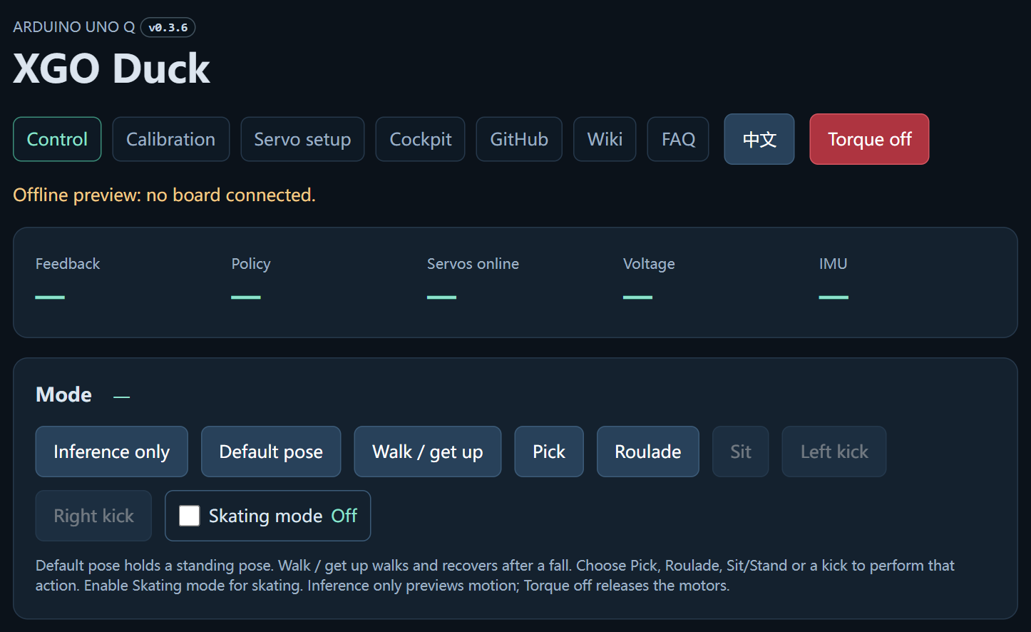
You operate the page: AI only checks or starts the existing software and opens the home page. It does not scan, change IDs or write parameters. Only one servo is connected in Step 4, so fewer than 15 online is expected. Screenshot addresses and counts are examples. A successful startup does not require manual installation reference again.
Connect the battery and one servo
Connect the battery and one servo to the expansion board, and turn its power switch on.
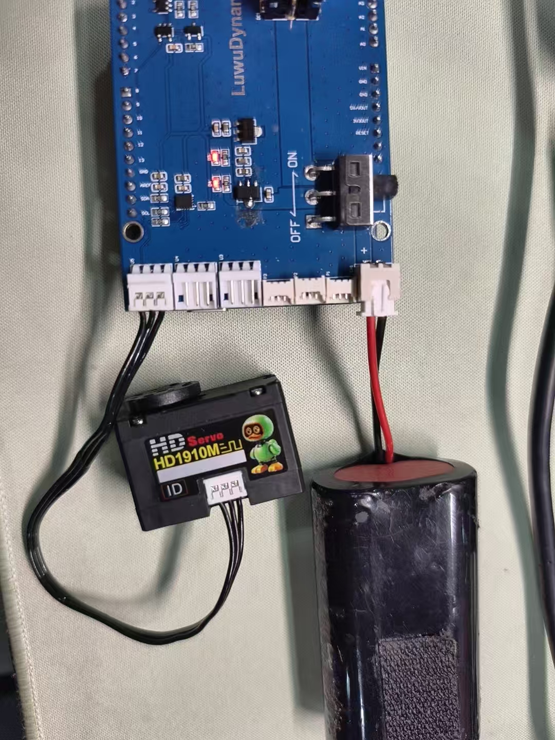
Connect only one servo at a time. Finish settings, ID verification and labeling before replacing it. A scan cannot distinguish multiple connected servos with the same ID.
Scan and select the servo
Click Servo setup at the top of the control page. Entering this page unloads all servo torque; support an assembled Duck first.
These instructions use v0.3.6. Screenshots show the English interface; use the device page's language switch at the top right to select English if needed. If you still see a combined voltage/overcurrent protection control, check your installed version.
- Connect only the servo you are setting up and wait for the page to confirm setup mode.
- Click Scan all IDs to scan IDs 0–253.
- Once found, click Stop scan to keep the results already collected.
- Click its ID in the results. New servos are usually ID 1; use the actual result for previously configured servos.
- Selecting the servo reads its parameters. The controls below reset its center, write KP/KD and change its ID.
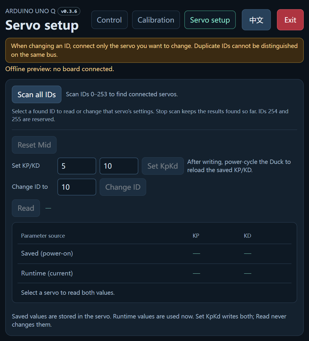
About the screenshots: These are offline renders of the original v0.3.6 interface showing control locations. No board was connected and no scan, write or test was performed. Empty values and disabled buttons are screenshot states; use your device's actual readbacks.
Set the center and parameters first
After selecting a servo, follow this sequence. Do not change the ID yet.
Parameters for all 15 servos
For v0.3.6, set KP 5 and KD 10 on all 15 servos, including mouth ID34; enable voltage and overcurrent protection separately; set the new threshold to 2 A. Choose the ID by installation position, then change and label it after setting the parameters. Left and right are from the robot's perspective. Swipe horizontally to read the table on a phone.
| Target ID | Joint | KP | KD | Voltage / overcurrent protection | Current threshold |
|---|---|---|---|---|---|
| 10 | Left leg · Hip yaw | 5 | 10 | Both enabled | 2 A |
| 11 | Left leg · Hip roll | 5 | 10 | Both enabled | 2 A |
| 12 | Left leg · Hip pitch | 5 | 10 | Both enabled | 2 A |
| 13 | Left leg · Knee | 5 | 10 | Both enabled | 2 A |
| 14 | Left leg · Ankle | 5 | 10 | Both enabled | 2 A |
| 20 | Right leg · Hip yaw | 5 | 10 | Both enabled | 2 A |
| 21 | Right leg · Hip roll | 5 | 10 | Both enabled | 2 A |
| 22 | Right leg · Hip pitch | 5 | 10 | Both enabled | 2 A |
| 23 | Right leg · Knee | 5 | 10 | Both enabled | 2 A |
| 24 | Right leg · Ankle | 5 | 10 | Both enabled | 2 A |
| 30 | Neck · Pitch | 5 | 10 | Both enabled | 2 A |
| 31 | Head · Nod | 5 | 10 | Both enabled | 2 A |
| 32 | Head · Yaw | 5 | 10 | Both enabled | 2 A |
| 33 | Head · Roll | 5 | 10 | Both enabled | 2 A |
| 34 | Mouth · Open / close | 5 | 10 | Both enabled | 2 A |
These are values to write in Servo setup, not joint angles. Reset the center of each servo now, and calibrate all zero positions against the diagrams in Step 6 after assembly.
Write and verify in order
| Order | Control | Action |
|---|---|---|
| 1 | Reset Mid | Click and wait for confirmation that the reset command was sent. The servo stays unloaded. Calibrate zero positions again after assembly in Step 6. |
| 2 | Set KP/KD | Enter 5 in KP and 10 in KD, then click Set KpKd. |
| 3 | Servo protection → Voltage protection | Click Enable on this row and wait for verification. |
| 4 | Servo protection → Overcurrent protection | Click Enable on this row and wait for verification. |
| 5 | Overcurrent protection → New threshold | Enter 2 A, click Write current threshold, and check the readback. A pre-filled 2 does not mean it has been written. |
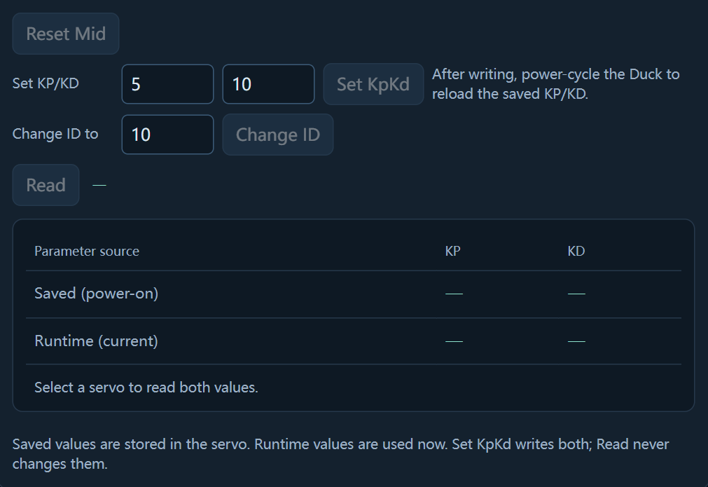
Entering values alone does not write them: click the corresponding button. KP/KD is read back automatically after writing; Read checks it again.
| Parameter source | Meaning | Expected values |
|---|---|---|
| Saved values (loaded at power-on) | Stored in the servo and loaded after power cycling. | KP 5, KD 10 |
| Running values (currently active) | Parameters the servo is using now. | KP 5, KD 10 |
The page should report that saved and running values match. For —, read errors or mismatched values, check the connection and read again before changing the ID. Follow the page's power-cycle instruction to load saved KP/KD, then scan, select and read again.
References: v0.3.6 servo instructions. Older software may have different temporary running values; compare both saved and running values as described here.
Enable each protection and check readbacks
Scroll to Servo protection. In v0.3.6, voltage and overcurrent protection each have their own Enable / Disable controls. Enable both.
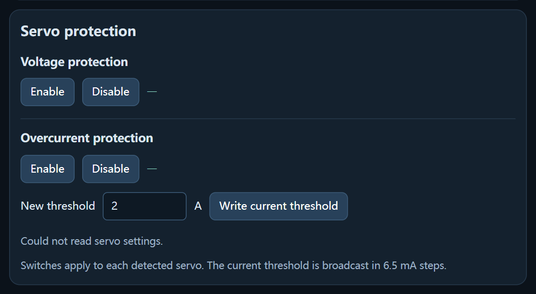
- Wait for protection-switch verification. In Servo readback, both protections for the ID should be Enabled.
- After the threshold broadcast, check each Saved threshold (A) is approximately 2 A. Resolution is 6.5 mA, so slight differences are expected.
- If a value is unread, unconfirmed or the ID is missing, check power and wiring, rescan and read again. A sent command does not prove the setting succeeded.
Different scopes: Protection switches apply individually to servos detected by the page; the current threshold broadcasts to every servo on the bus. Neither affects only the selected ID. Keep only one servo connected during this step.
Change the ID last and verify it
After center and parameter setup, enter the target under Change ID to. For example, enter 10 to change ID 1 to 10, then click Change ID.
Wait for ID 1 → 10 · verified. This confirms the new ID passed verification.
The page clears the old scan results after a successful change and asks you to scan and select the new ID. Rescan and confirm ID 10 appears; do not keep using ID 1.
10 is only this example. Assign each servo its own ID without duplicates: 10–14, 20–24 and 30–34. See the Step 5 ID diagram for positions. If the target ID is occupied, there is no response or verification fails, check the connection and IDs before treating the change as successful.
Label it immediately, then replace it
- After success, attach a new ID label or write the number on the servo immediately. If it became ID 10, label it 10.
- Turn off servo power before connecting the next servo. Keep only one connected.
- Power on, scan and select the new servo.
- Repeat Reset center and parameters → Compare saved and running values → Change ID → Verify → Label immediately.
Step complete: Every configured servo has verified settings and an ID label matching its actual ID, ready for assembly.
After assembly: single-servo installation check
After Step 5, use Single-servo installation check to confirm that an ID matches the physical joint. You can skip this while only assigning IDs.
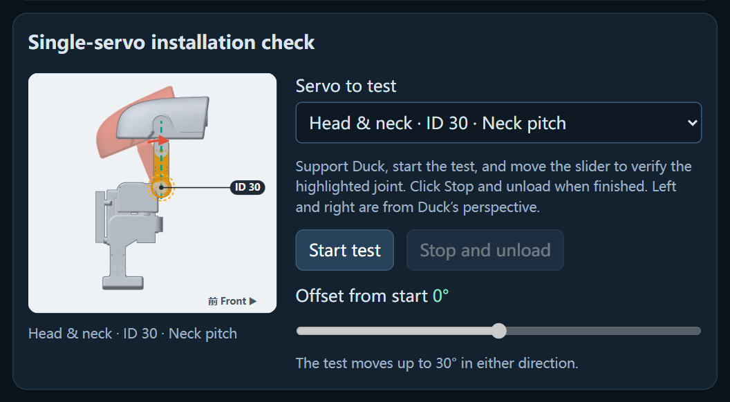
- Support Duck securely with room for the joint to move. Left and right are from Duck's perspective.
- Choose a configured ID under Test servo, and identify the expected joint in the diagram.
- Click Start test, then move the slider a small amount and observe whether only that joint moves. The maximum range is ±30° relative to the test's starting position; this does not set the zero position.
- Click Stop and unload before selecting another ID. If the wrong joint moves, stop and check IDs and assembly.
The test automatically unloads after 10 seconds without a target-angle adjustment. Exiting, disconnecting or sustained loss of position feedback also ends it. Still use Stop and unload yourself, and keep the robot supported.
This check does not replace calibration. Once positions match, complete IMU and servo-center calibration in Step 6.