 Wiki
Assemble the body after assigning all servo IDs. Then fit the camera, audio, light and ToF components and complete the wiring below. Keep power disconnected throughout mechanical assembly and cable changes.
3D assembly reference
Optional visual reference. Open the English 3D assembly viewer on Digimals to inspect part positions and build steps. Keep this chapter open for the current audio/video photos and wiring instructions.
Assemble the body
Use the labels and orientation in these 25 English illustrations. Check screw sizes against your actual kit. For offline use, download the bilingual body assembly PDF (Chinese and English, 25 pages, about 4.3 MB).
25 illustrated body assembly steps
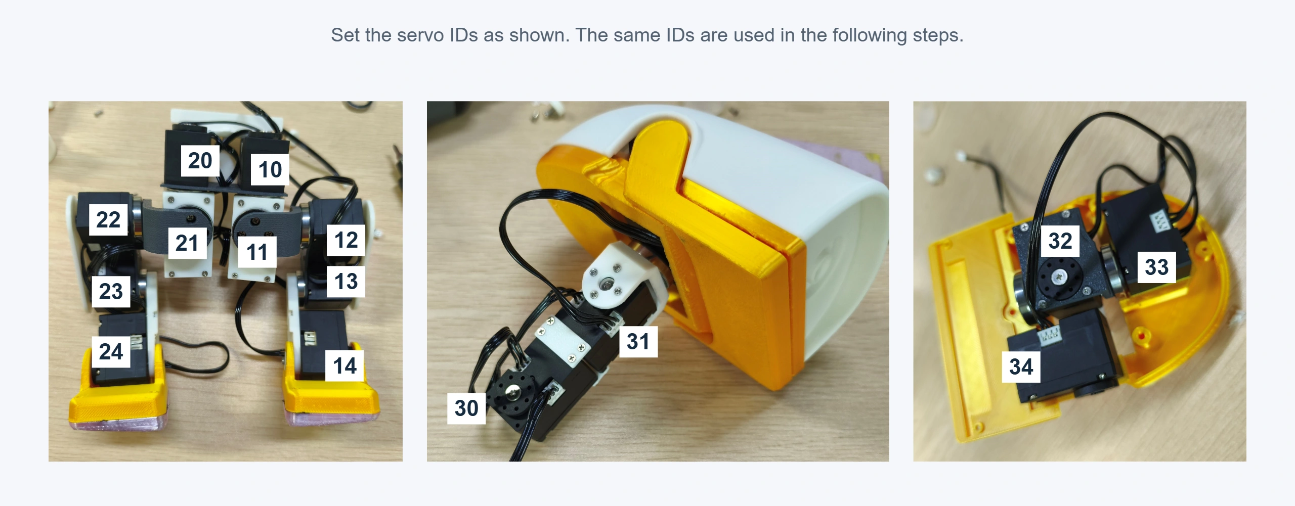
01 · Check servo IDs
Verify the positions for IDs 10–14, 20–24 and 30–34. Each joint keeps its assigned ID after assembly.
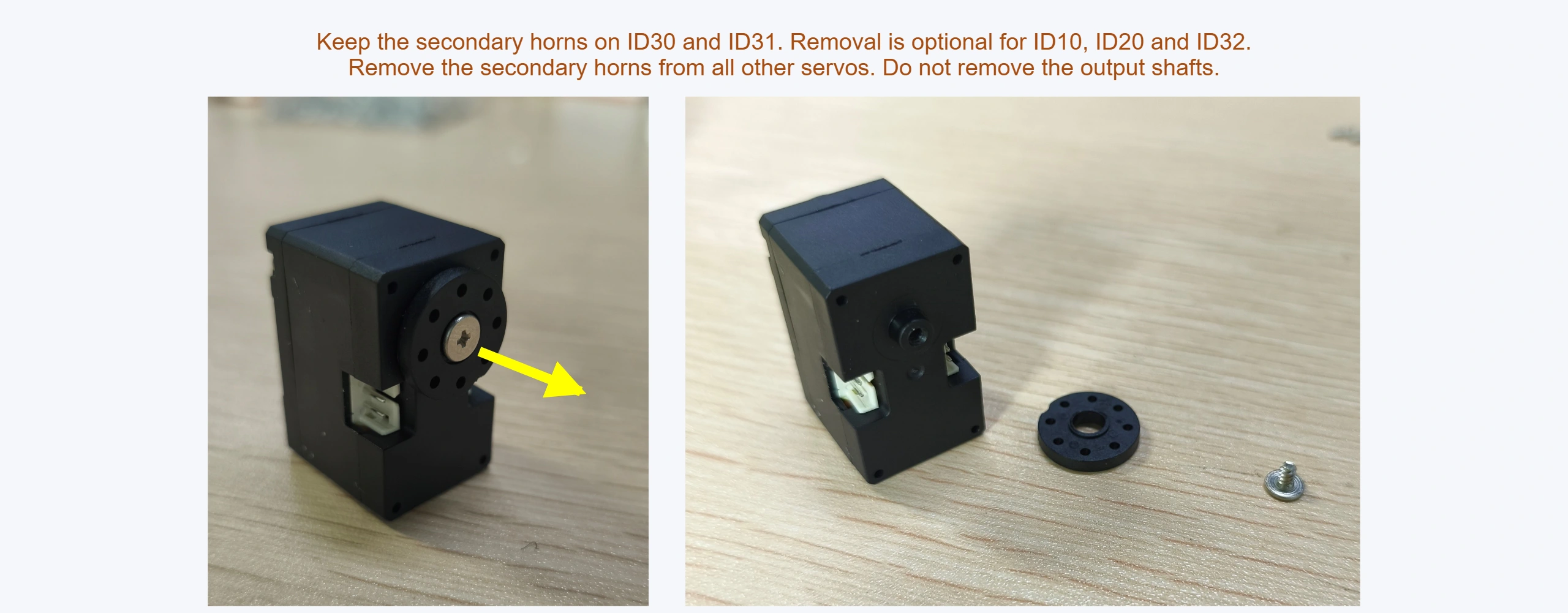
02 · Prepare the secondary horns
Keep the secondary horns on IDs 30 and 31; IDs 10, 20 and 32 may be removed as shown. Remove the others as illustrated. Remove only the secondary horn, not the output shaft.
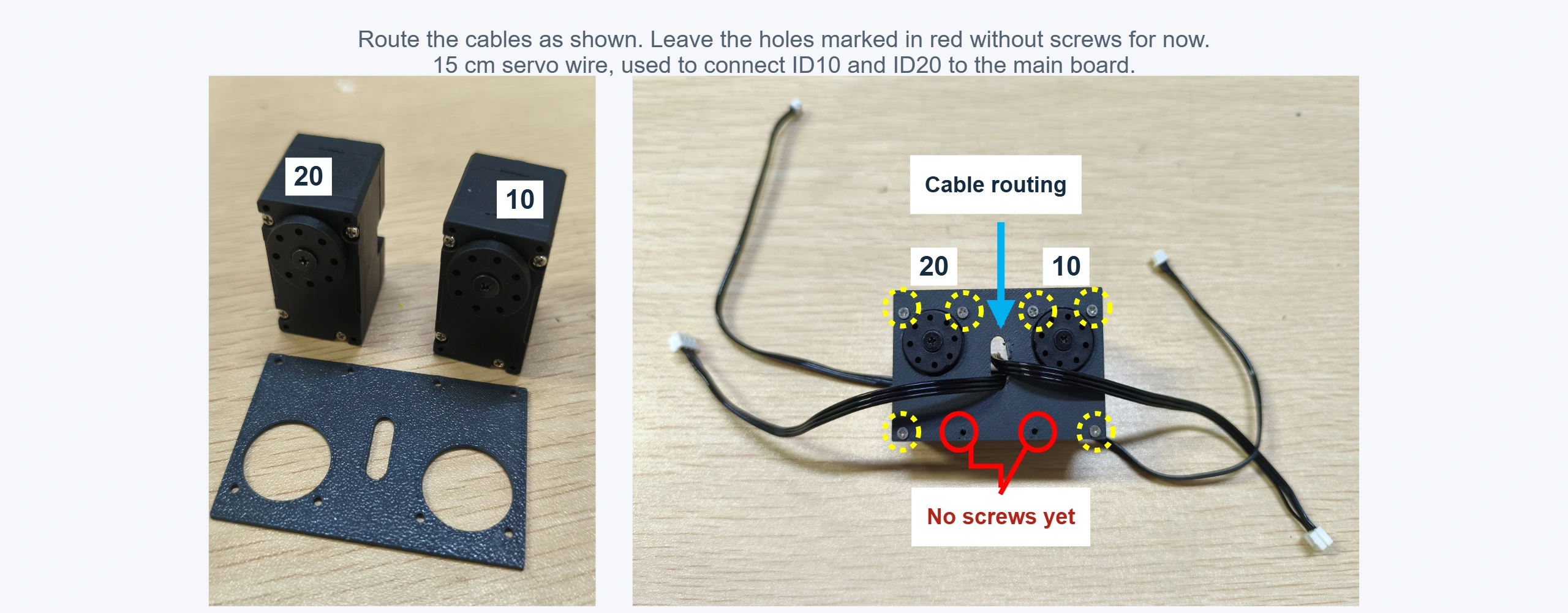
03 · Base servos and connecting plate
Combine IDs 10 and 20 with the plate and route cables as shown. Leave the two red-circled holes without screws for now. Use 15 cm servo cables to the board. Six M2 × 6 countersunk self-tapping screws.
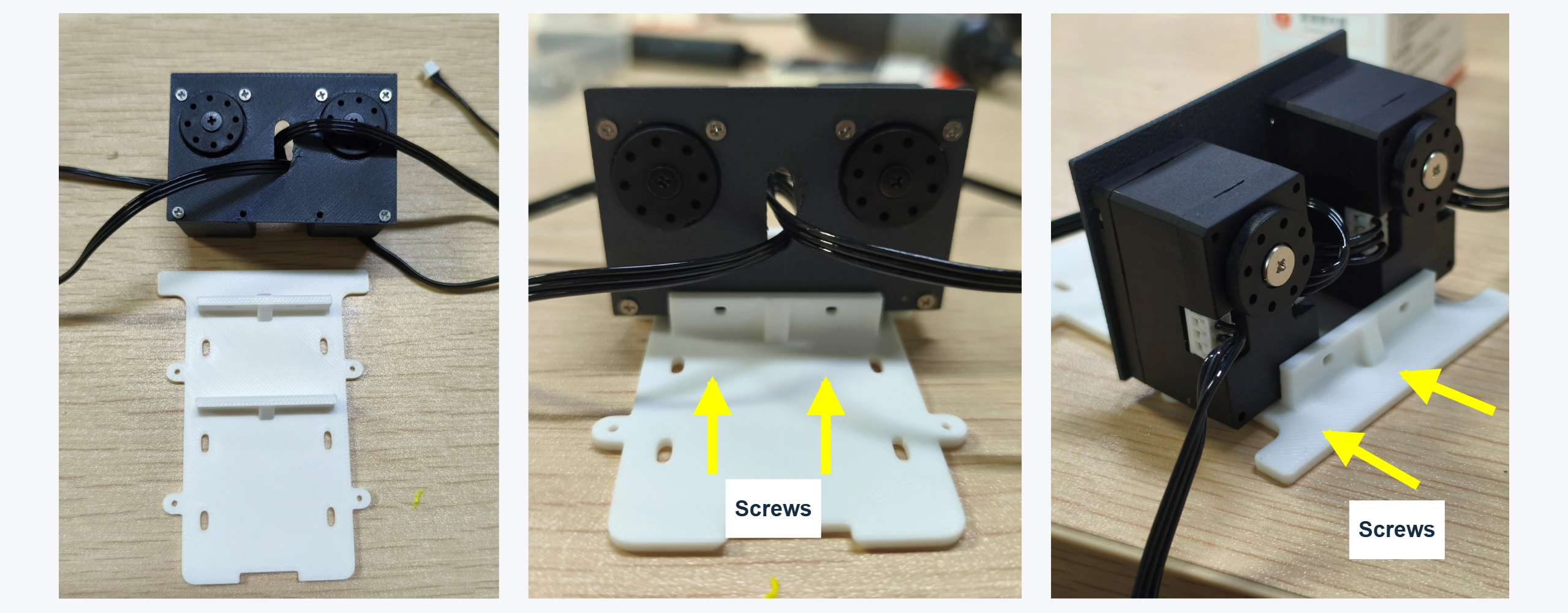
04 · Fit the base bracket
Align the bracket with the servo assembly. Four M2 × 6 countersunk self-tapping screws.
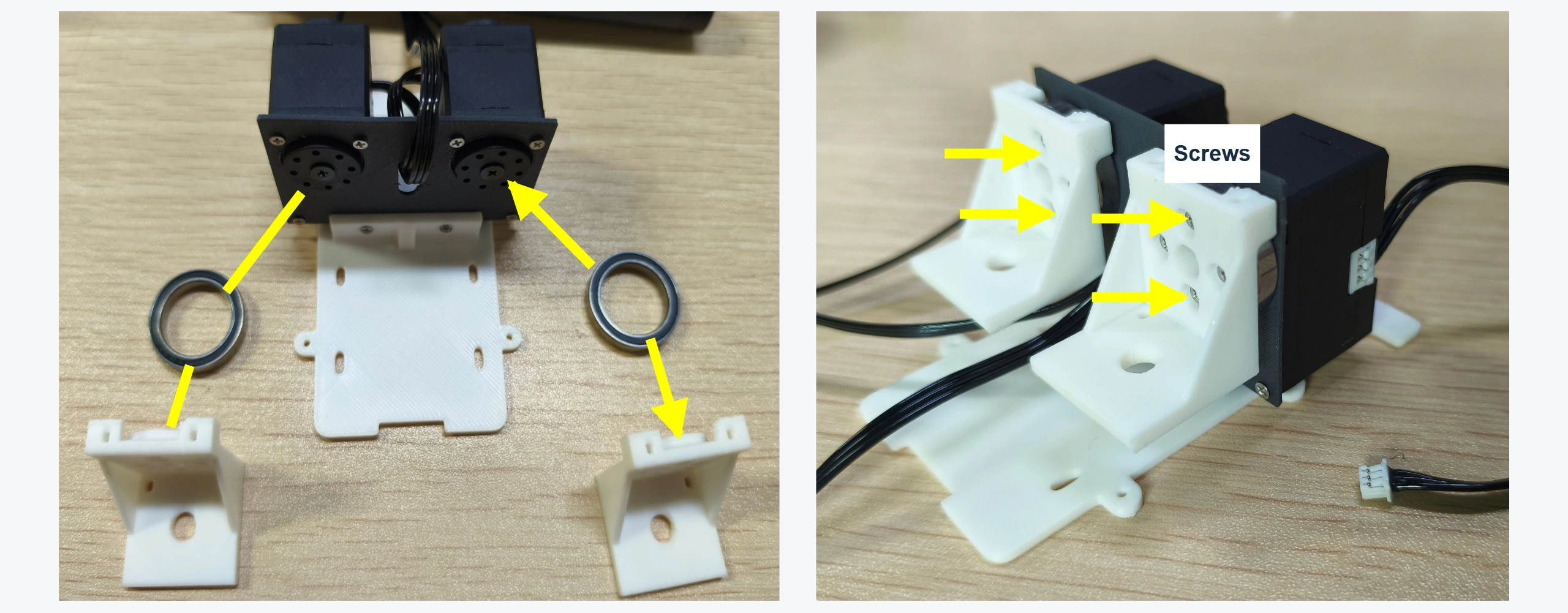
05 · Fit side brackets and bearings
Place the bearings and install both side brackets. Eight M2 × 6 countersunk self-tapping screws.
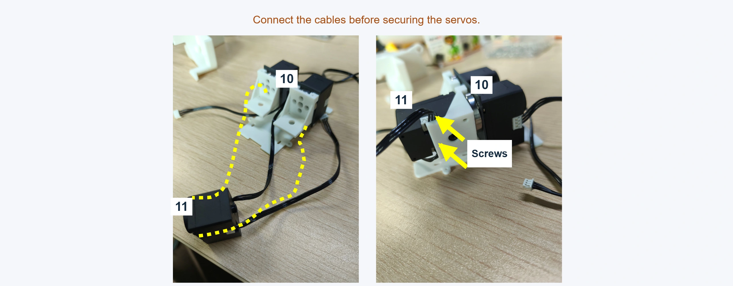
06 · Connect the leg servos
Connect cables before fixing the servos; check the illustrated orientation of IDs 10 and 11. Four M2 × 6 countersunk self-tapping screws.
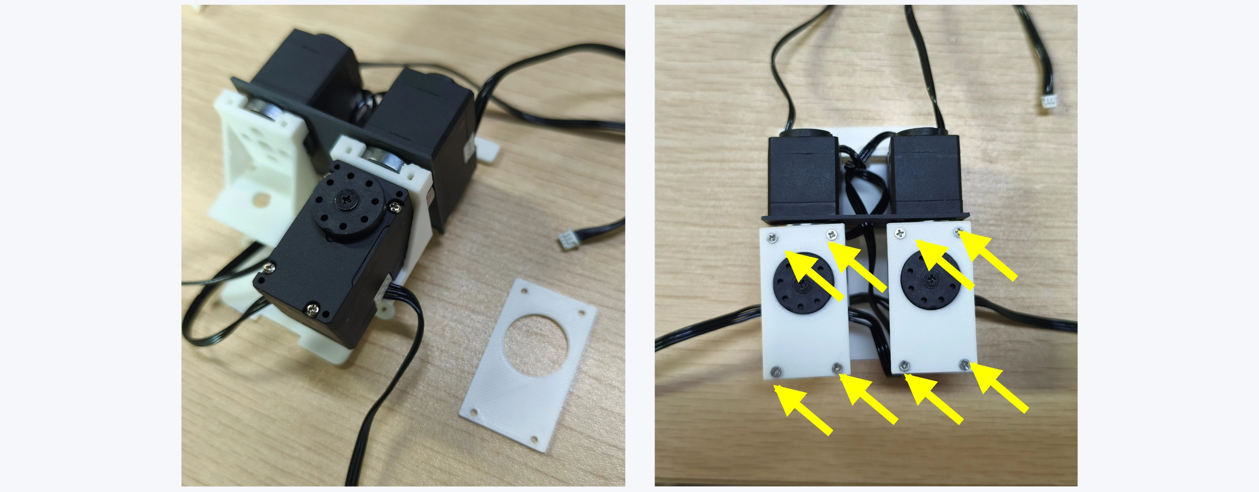
07 · Fix the leg connecting plates
Install the plates at the marked holes. Eight M2 × 6 countersunk self-tapping screws.
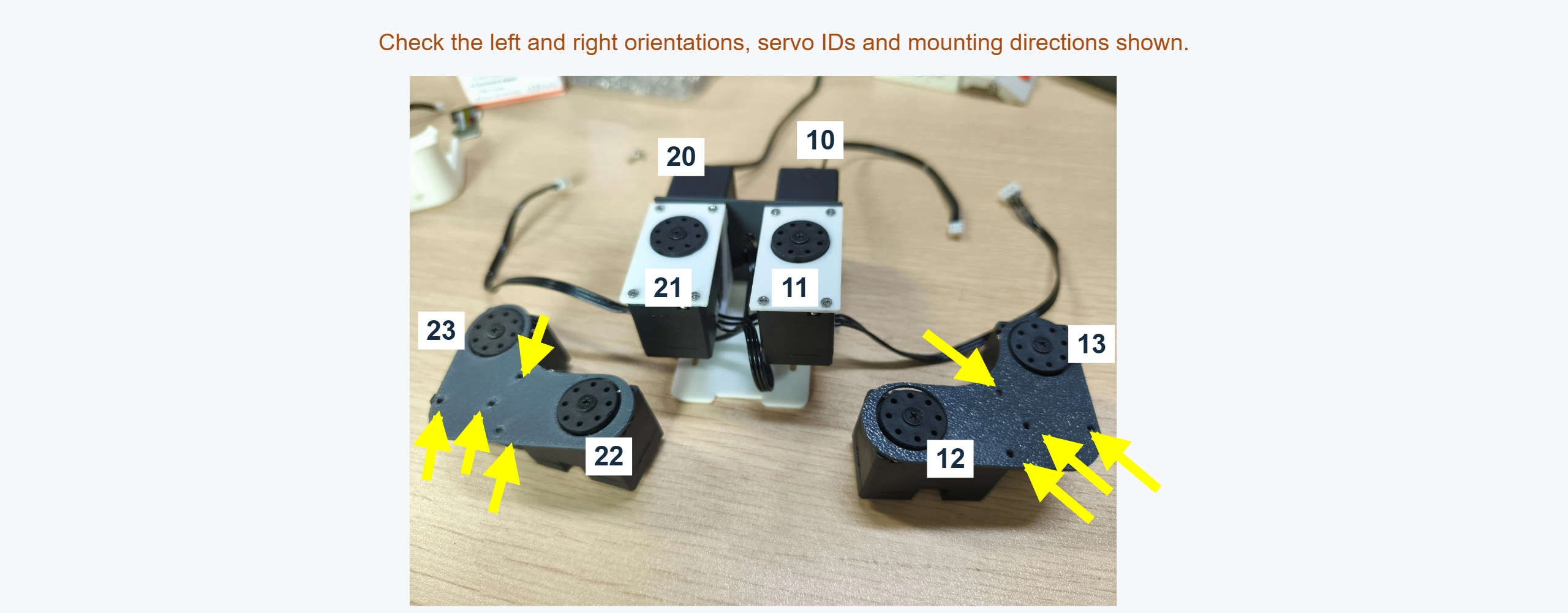
08 · Assemble the left and right leg servos
Assemble IDs 12 and 13 and IDs 22 and 23, checking the side and orientation. Eight M2 × 6 countersunk self-tapping screws.
09 · Install the leg linkages
Insert the bearings and fit the linkages with the orientation shown. Four M2 × 6 countersunk self-tapping screws.
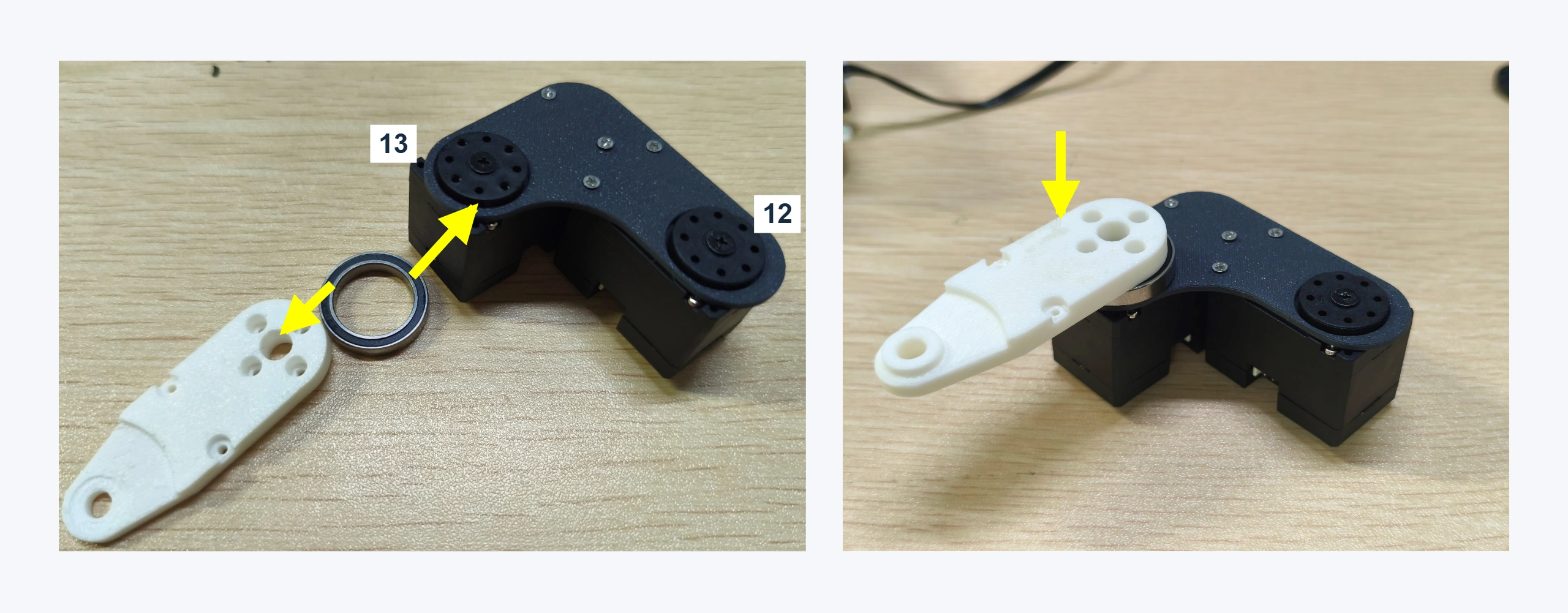
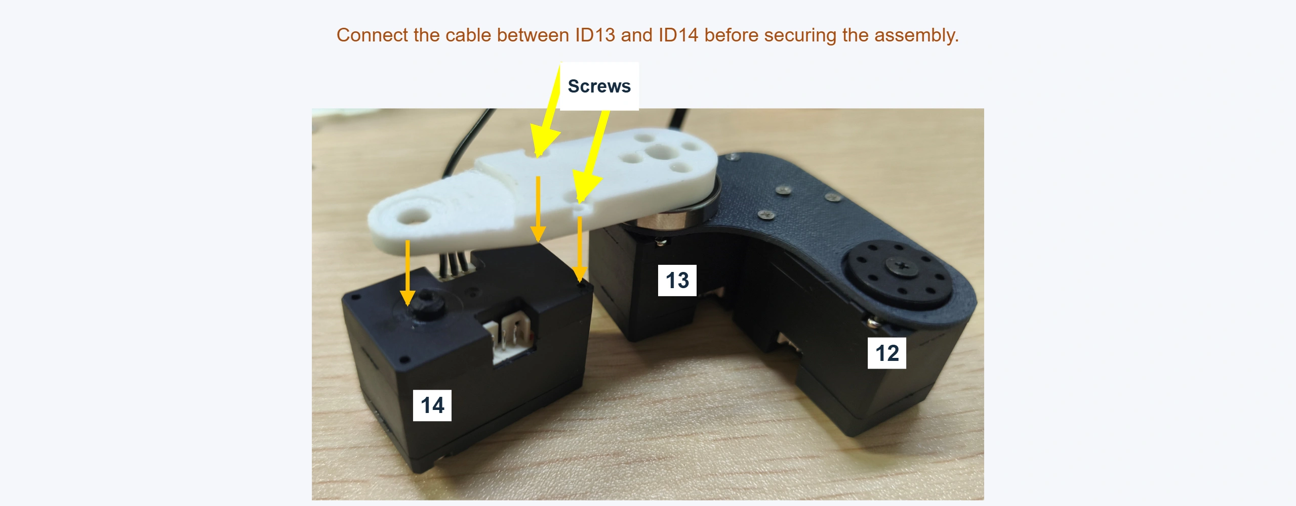
10 · Connect the foot servo
Connect the cables for IDs 13 and 14 before aligning and fixing the foot servo. Two M2 × 6 countersunk self-tapping screws.
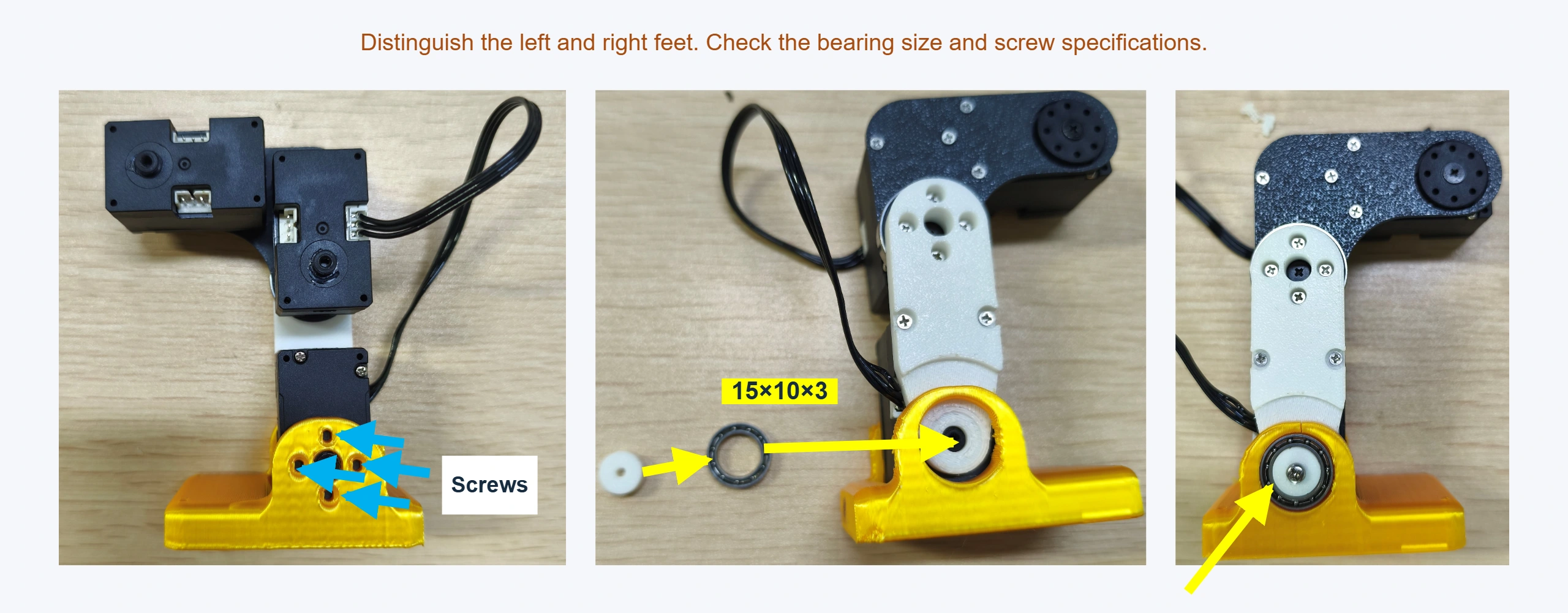
11 · Install left and right feet
Distinguish the sides and install the feet and 15 × 10 × 3 bearings. The left illustration uses four M2 × 6 countersunk screws; the right fixing position uses M2.3 × 8 flat-head self-tapping screws.
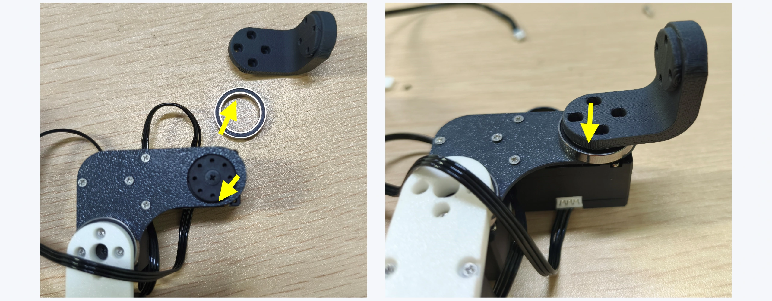
12 · Install upper leg brackets
Fit bearings and secure the upper leg brackets. Four M2 × 6 countersunk self-tapping screws.
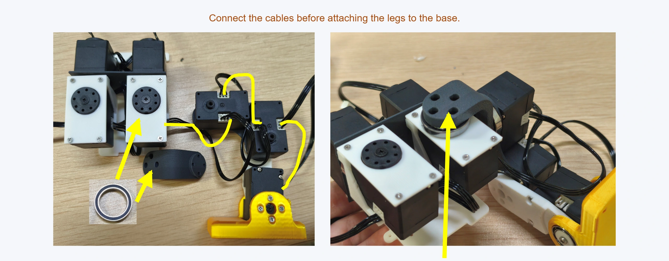
13 · Join legs and base
Connect the cables before fitting the legs. Check bearings and cable routes. Four M2 × 6 countersunk self-tapping screws.
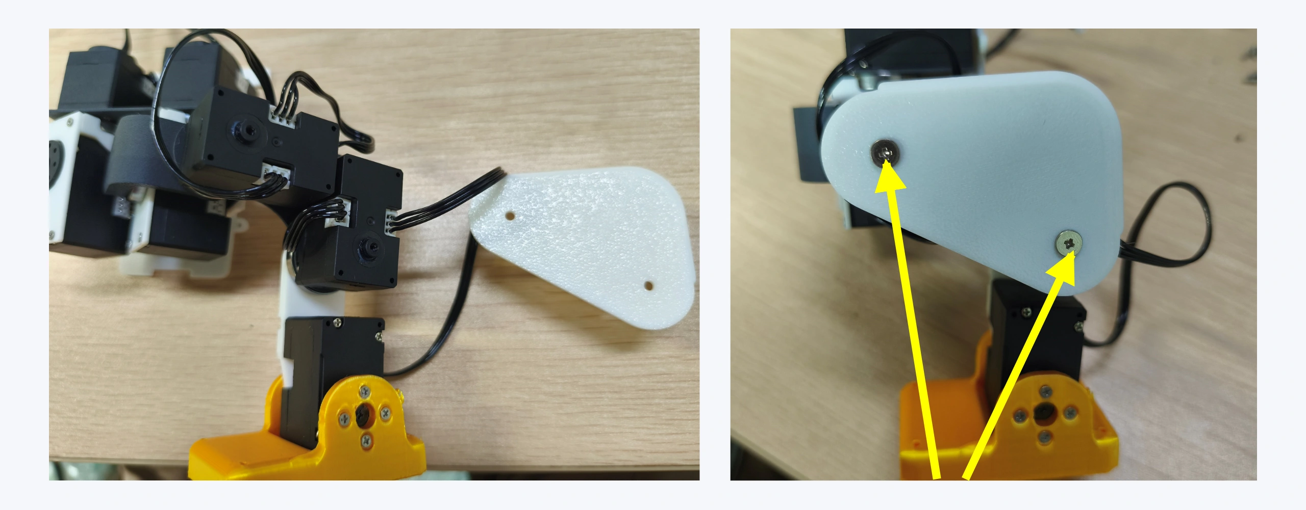
14 · Fit leg side plates
Use two M2.3 × 4 flat-head self-tapping screws supplied with the secondary horn.
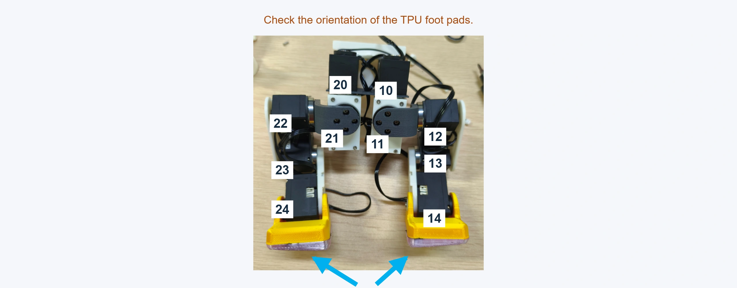
15 · Install TPU foot pads
Check the pad orientation and both leg IDs before fitting.
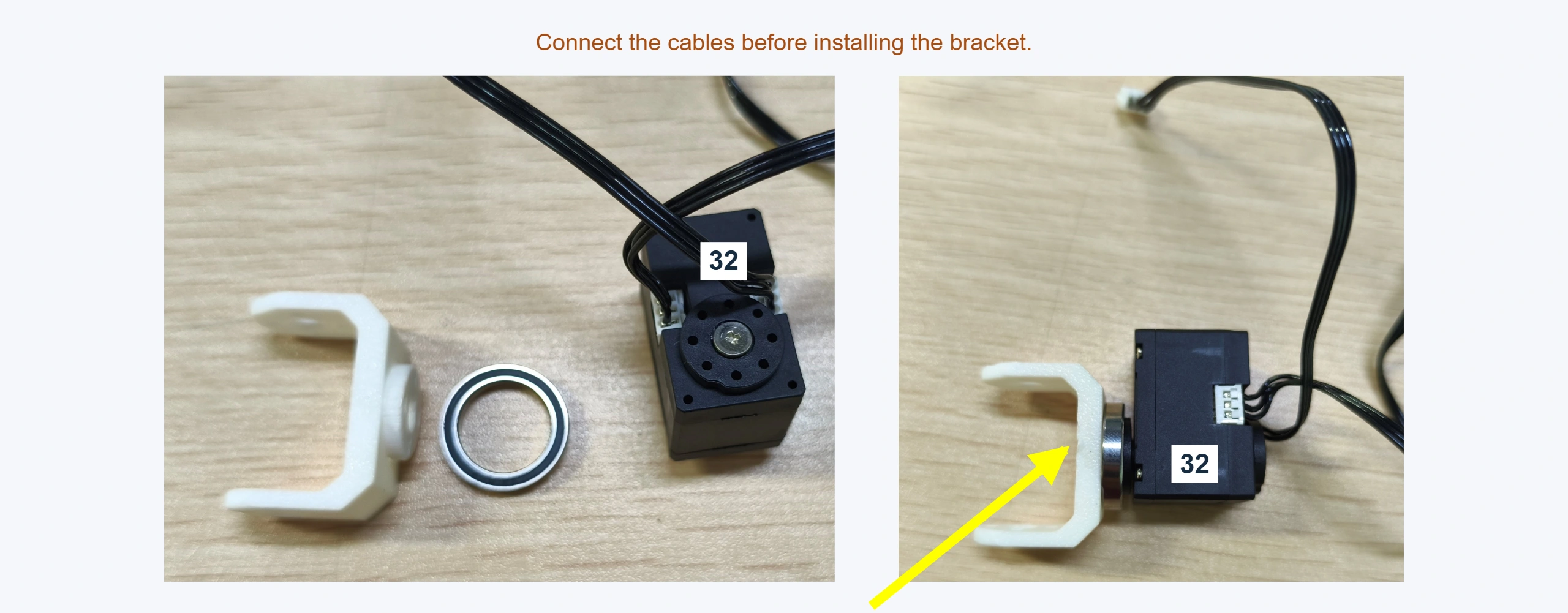
16 · Fit the ID 32 bracket
Connect its cable first, then install the bracket and bearing. Four M2 × 6 countersunk self-tapping screws.
17 · Fit the ID 33 bracket
Connect the lower cable first, then install the bracket and two bearings. Four M2 × 6 countersunk self-tapping screws.
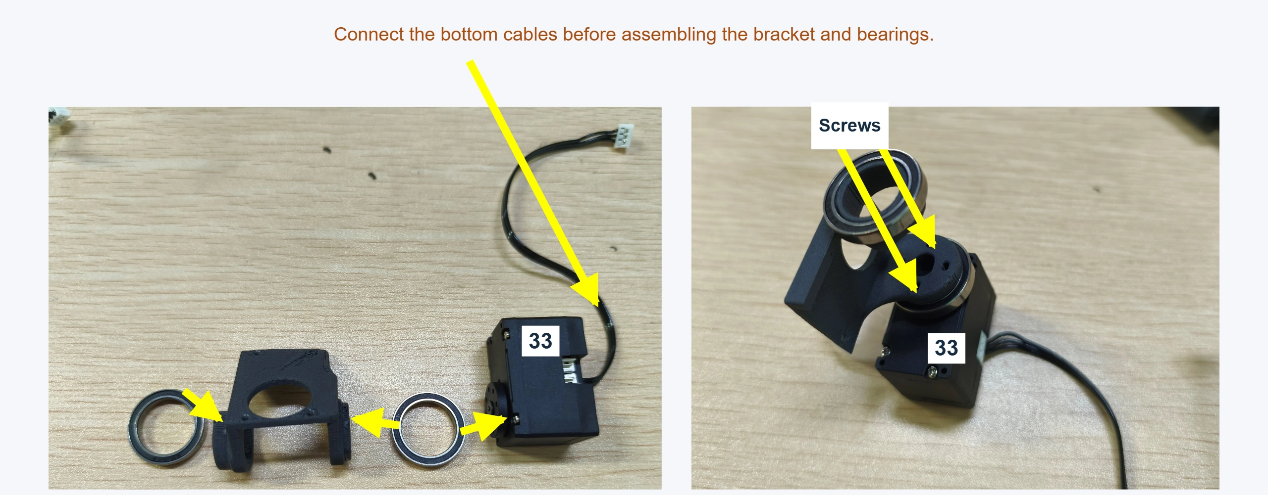
18 · Join IDs 32 and 33
Connect the head brackets and check cable routing. Four M2 × 6 countersunk self-tapping screws.
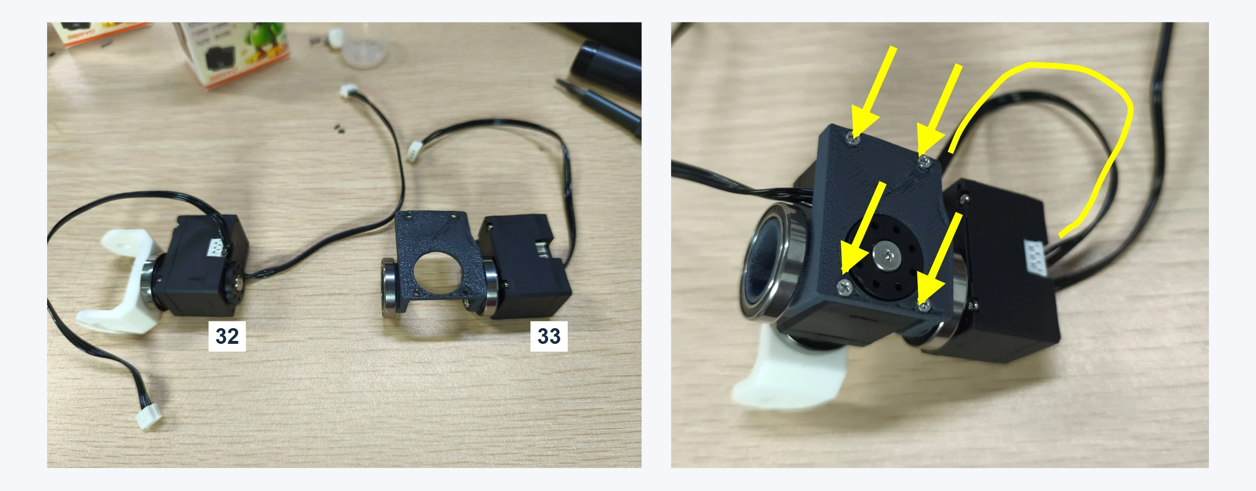
19 · Fit ID 34 and head shell
Place the servo and head assembly in the shell; route and fix as shown. Four M2 × 6 countersunk self-tapping screws.
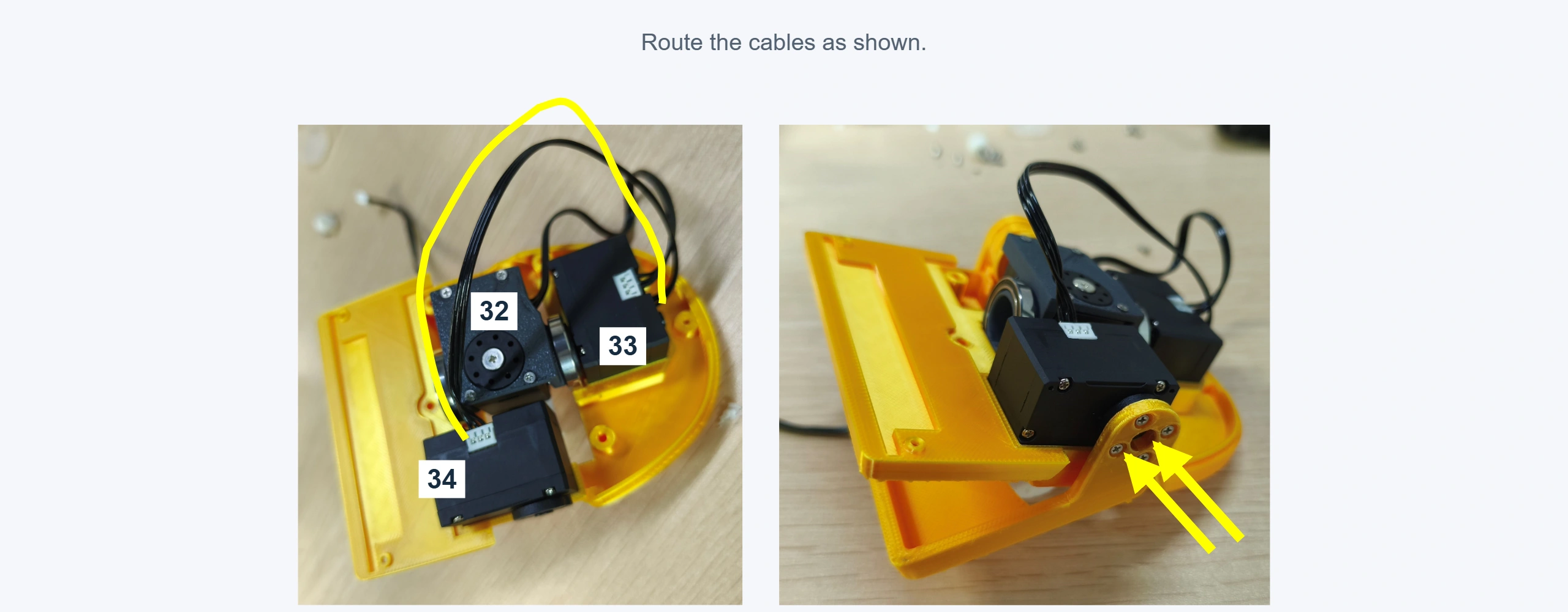
20 · Secure shell and brackets
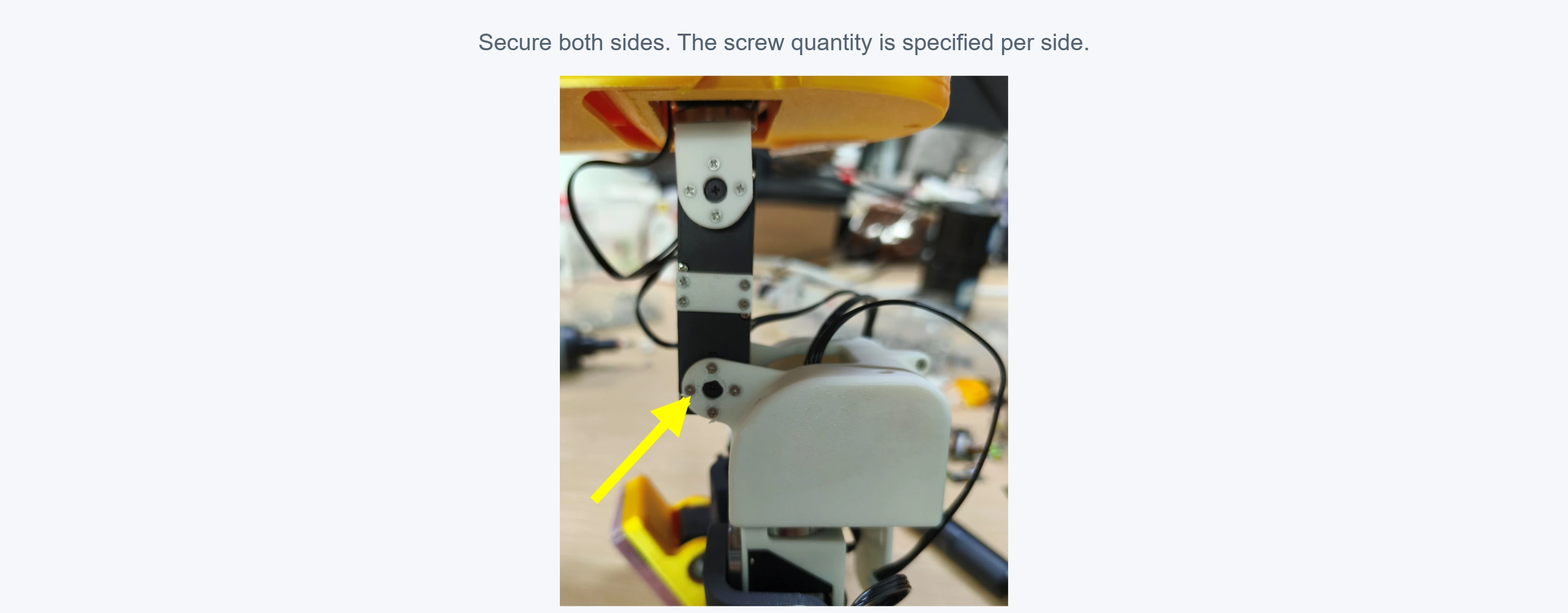
Secure both sides at the illustrated holes: four M2 × 6 screws on the left and three on the right.
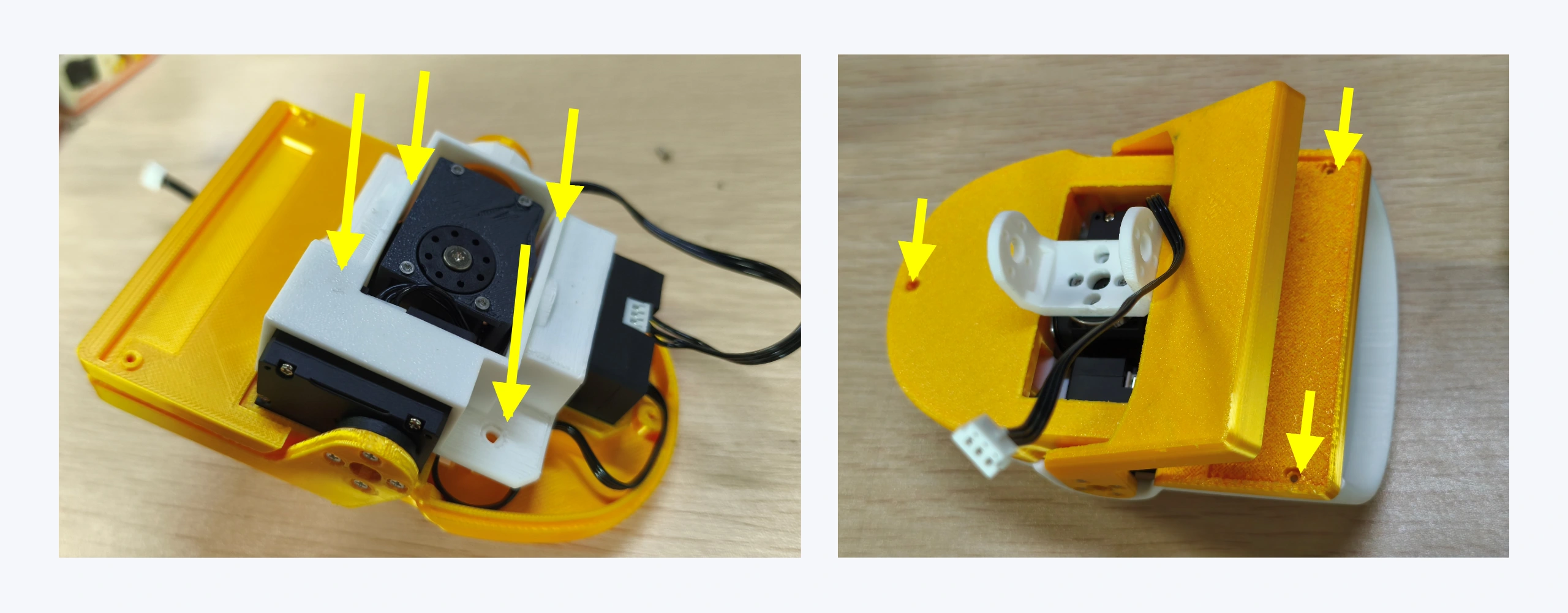
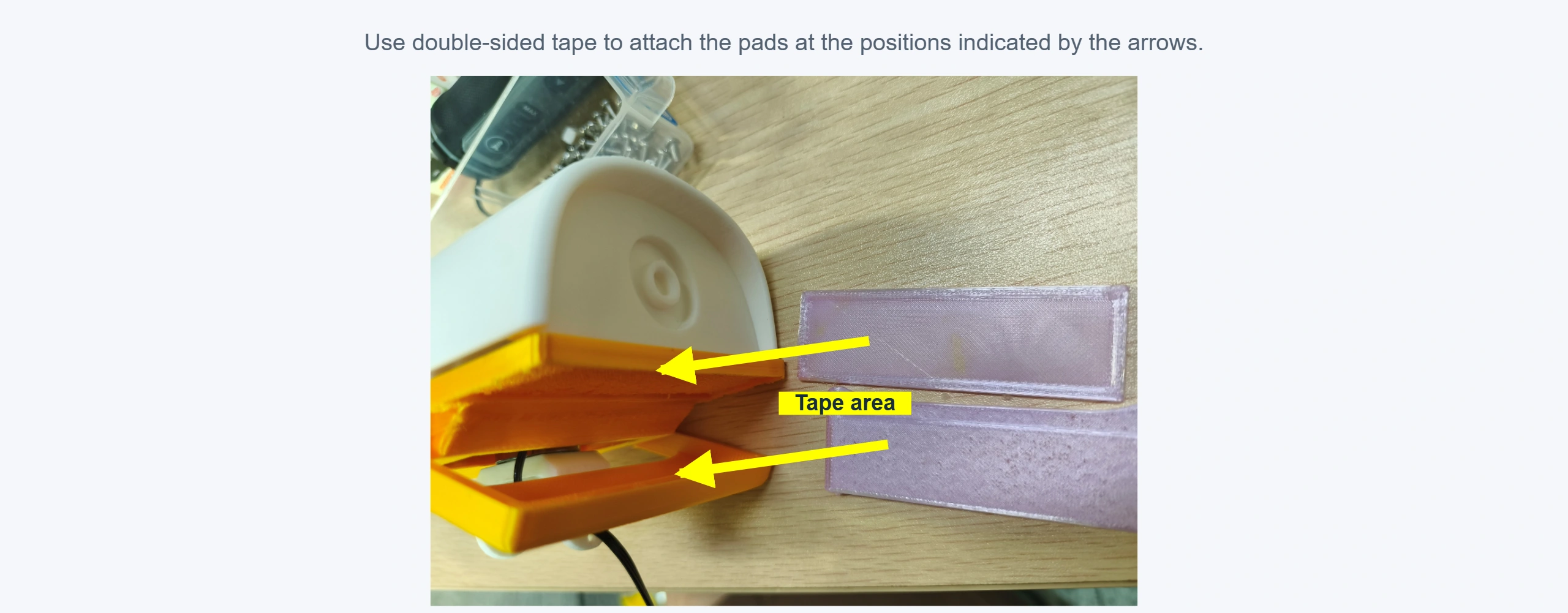
21 · Attach the soft pads
Use double-sided tape at the illustrated locations.
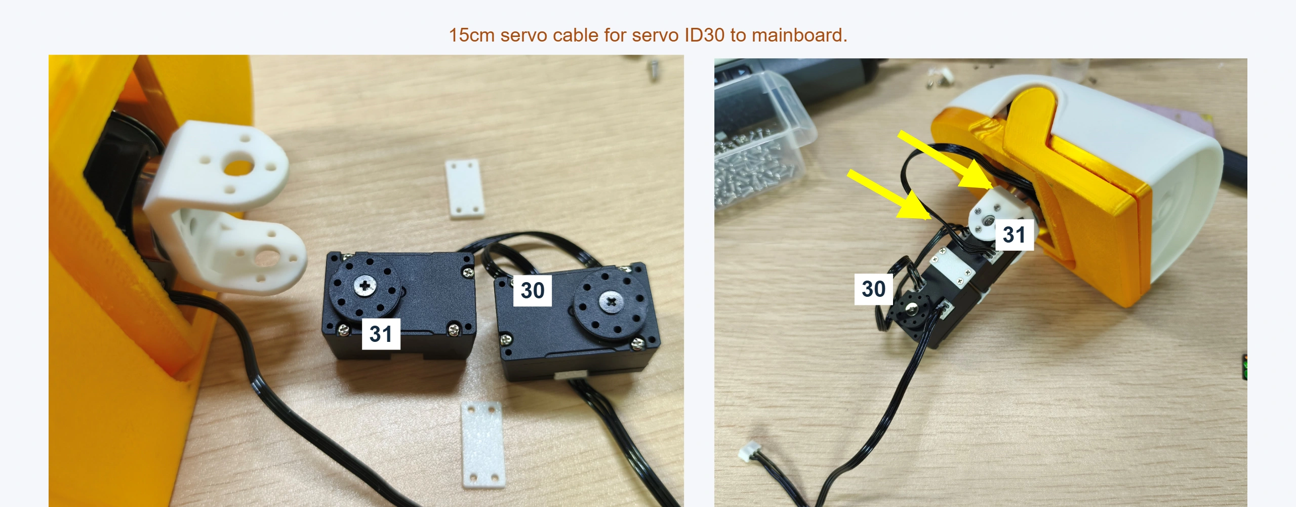
22 · Connect IDs 30 and 31
Assemble the neck and secure both sides. ID 30 connects to the board using a 15 cm cable. Sixteen M2 × 6 countersunk self-tapping screws.
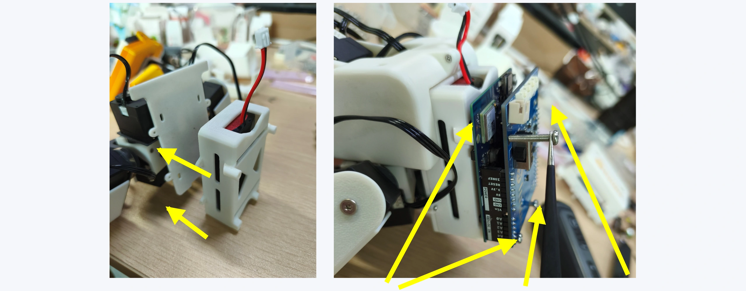
23 · Install the battery bracket and board
Fix the bracket and circuit board at the shown positions. Four M3 × 16 round-head machine screws.
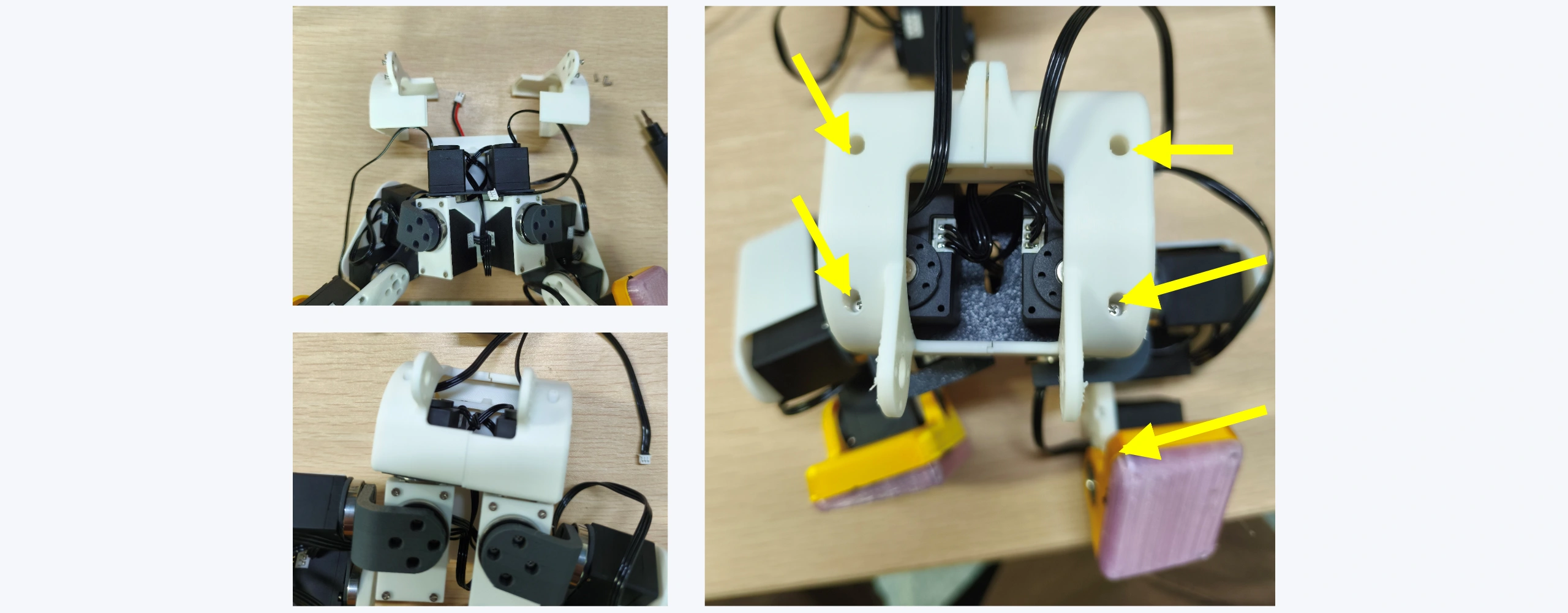
24 · Fit the upper bracket
Install and fix the bracket; check that no cable is trapped. Four M2 × 6 countersunk self-tapping screws.
Fit an expansion-board protective shell
We recommend fitting the protective shell before rolling or performing fall-and-recovery movements. Without the shell, impacts during these movements can easily damage the circuit board.
The latest protective-shell print files are available on the LuwuDynamics MakerWorld profiles below. Choose one of the following two shells to match your expansion-board version; you do not need to print both.
| Expansion-board version | Print file |
|---|---|
| V1 | Plate 7 · V1 Backpack shell |
| V1.1 | Plate 8 · V1.1 Backpack shell |
Print files: MakerWorld China · MakerWorld Global
25 · Join the upper and lower assemblies
Fix both sides, four M2 × 6 countersunk self-tapping screws per side. Check fasteners, joint travel and cable slack.
Skating wheel installation
Follow this video to assemble the skating wheels before continuing with the audio/video components below. Duration: about 5 minutes 4 seconds. Use full screen to inspect the assembly details.
Install the audio/video components
Updated 13 November 2026: the following 15 steps use the current 24 official photographs. The fill-light routing, rear camera-board view and speaker wiring photos include the latest revisions. Click a photo to enlarge it.
15 illustrated audio/video installation steps
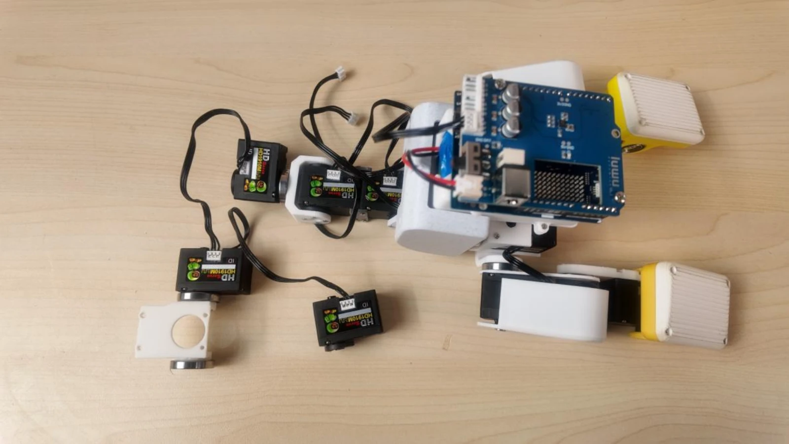
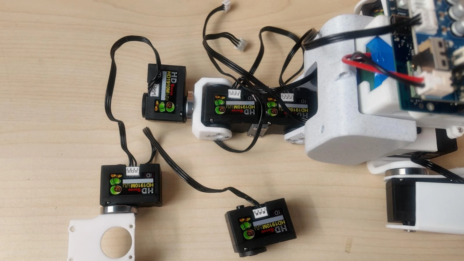
01 · Open the head
Disconnect power, then open the head to expose the servos and bracket as shown.
Organize the wires and keep every removed screw and part.
02 · Prepare the components
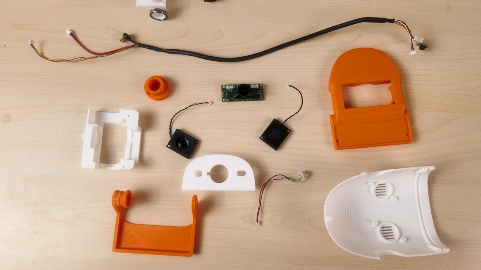
Prepare the camera, ToF sensor, fill light, two speakers, head parts and wiring harness.
Prepare M3 × 4 and M2 × 6 screws.
03 · Mount the ToF sensor
Position the ToF sensor at the side of its mounting plate and align the two holes.
Fasten it with two M3 × 4 screws; match the connector orientation in the assembled photo.
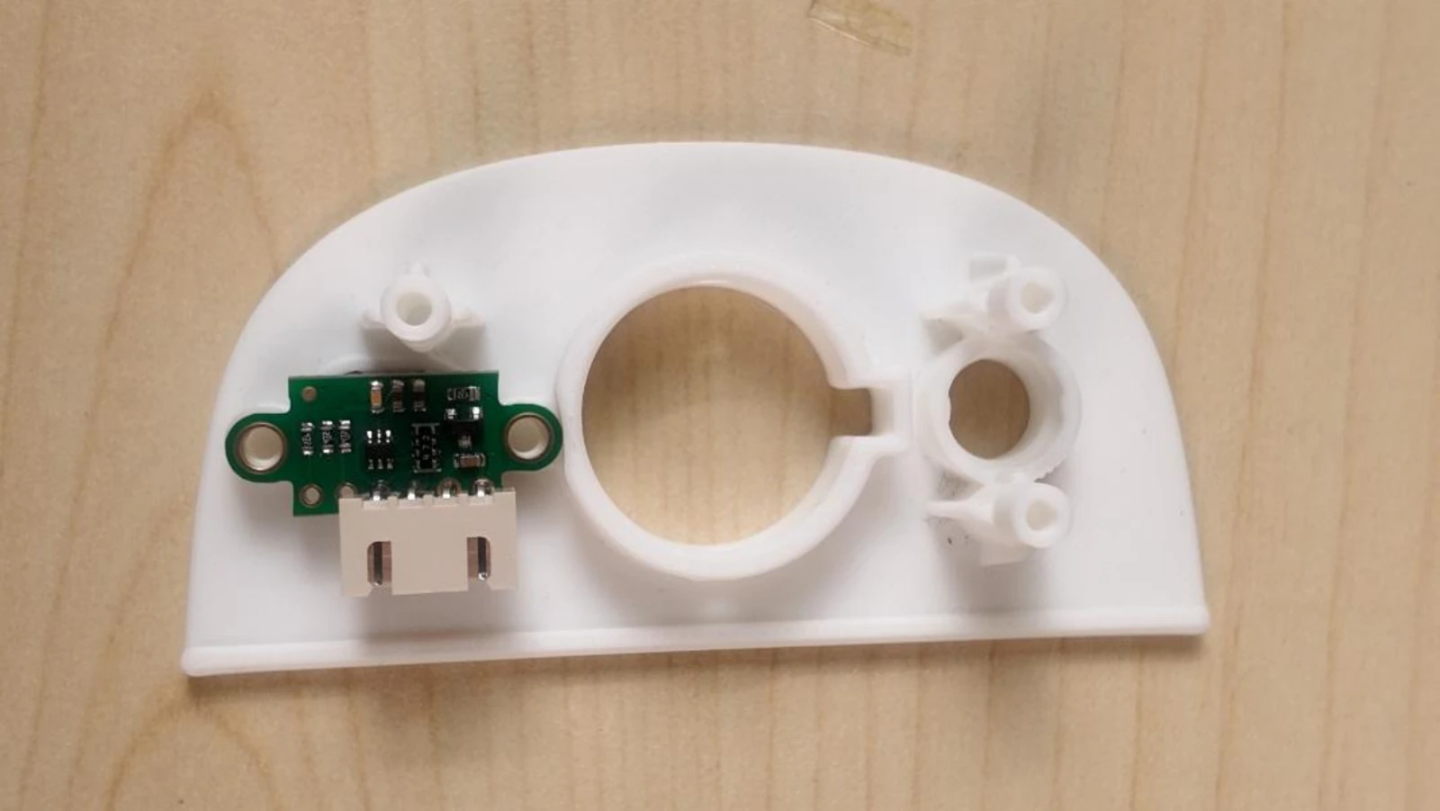
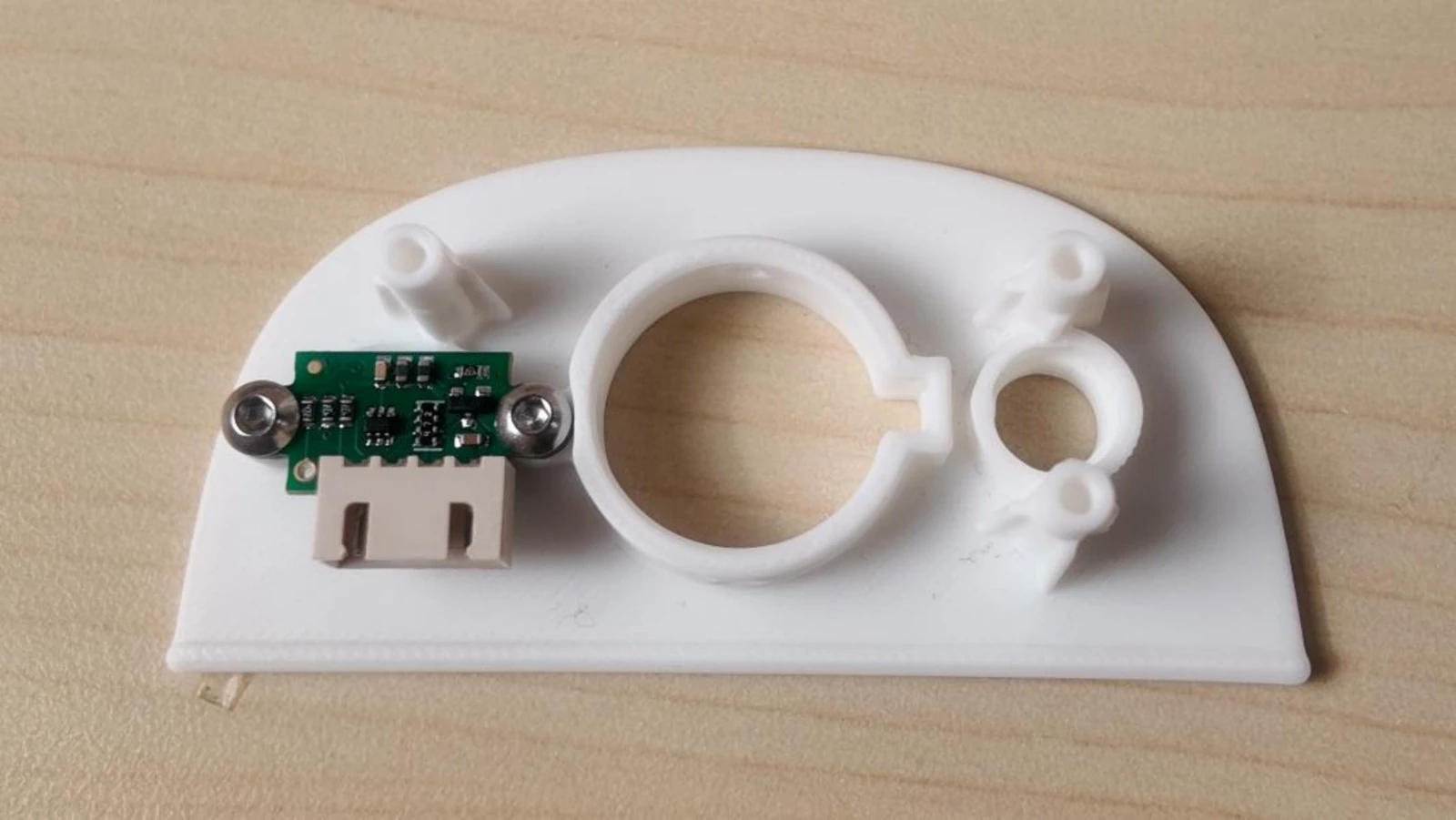
04 · Fit the fill light
Insert the fill light in the small round hole on the other side of the plate, facing outward.
Route its wires behind the plate and keep the metal pins from touching each other.
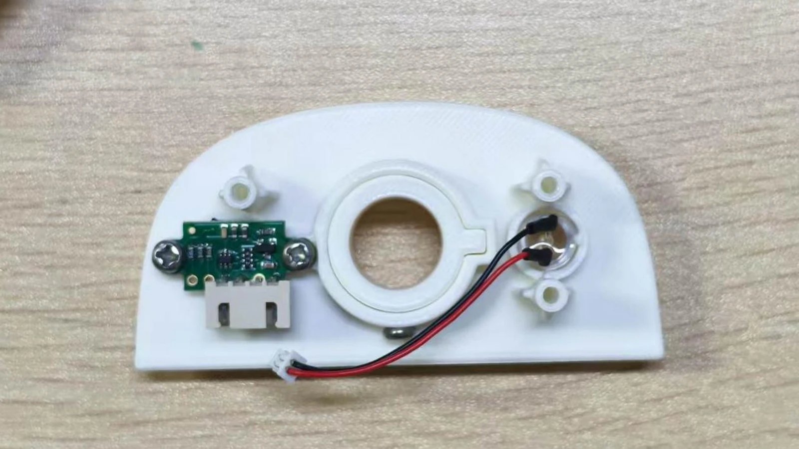
05 · Fit the lens holder
Align the orange lens holder with the central hole and notch in the plate.
Use M3 × 4 screws at the lens-holder fixing positions.
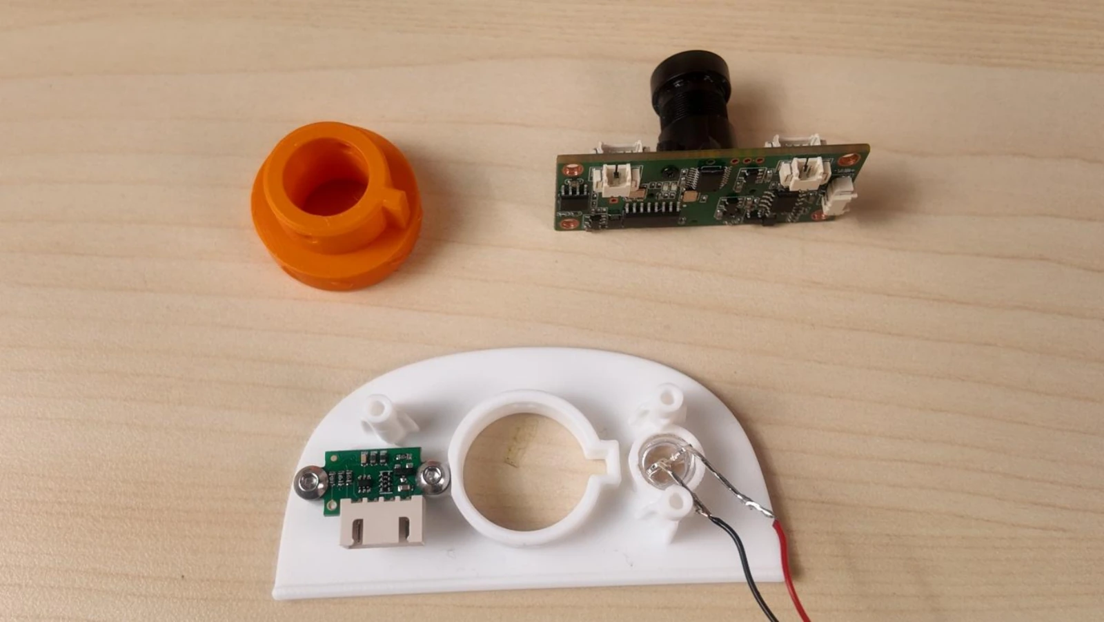
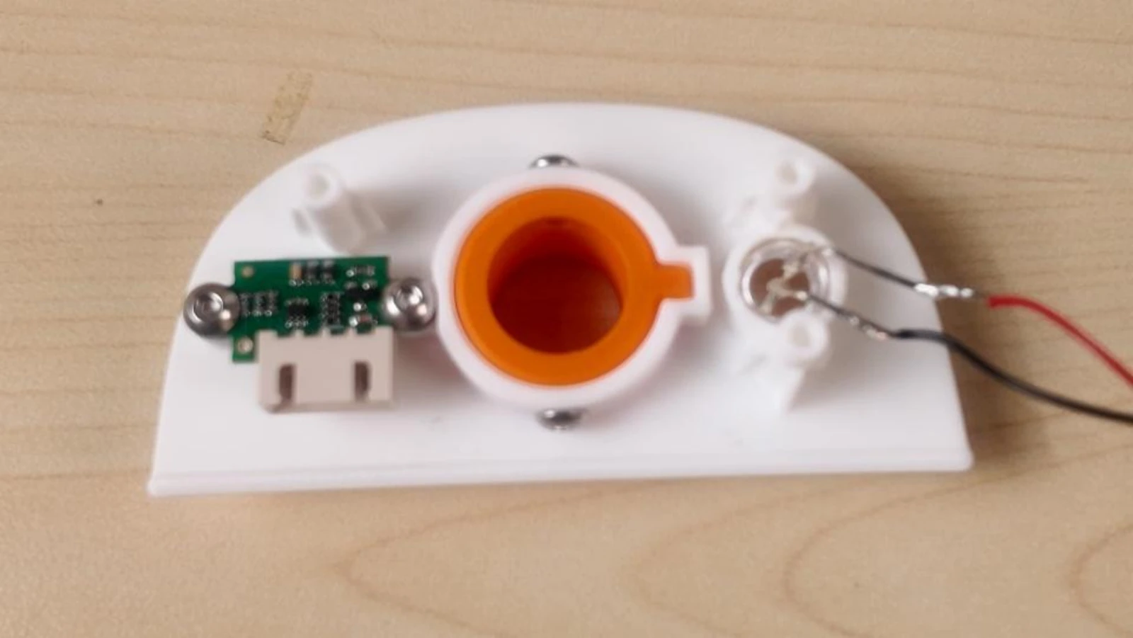
06 · Secure the camera module
Align the camera module and lens holder, then seat the module against the plate.
Secure the camera board with M3 × 4 screws.
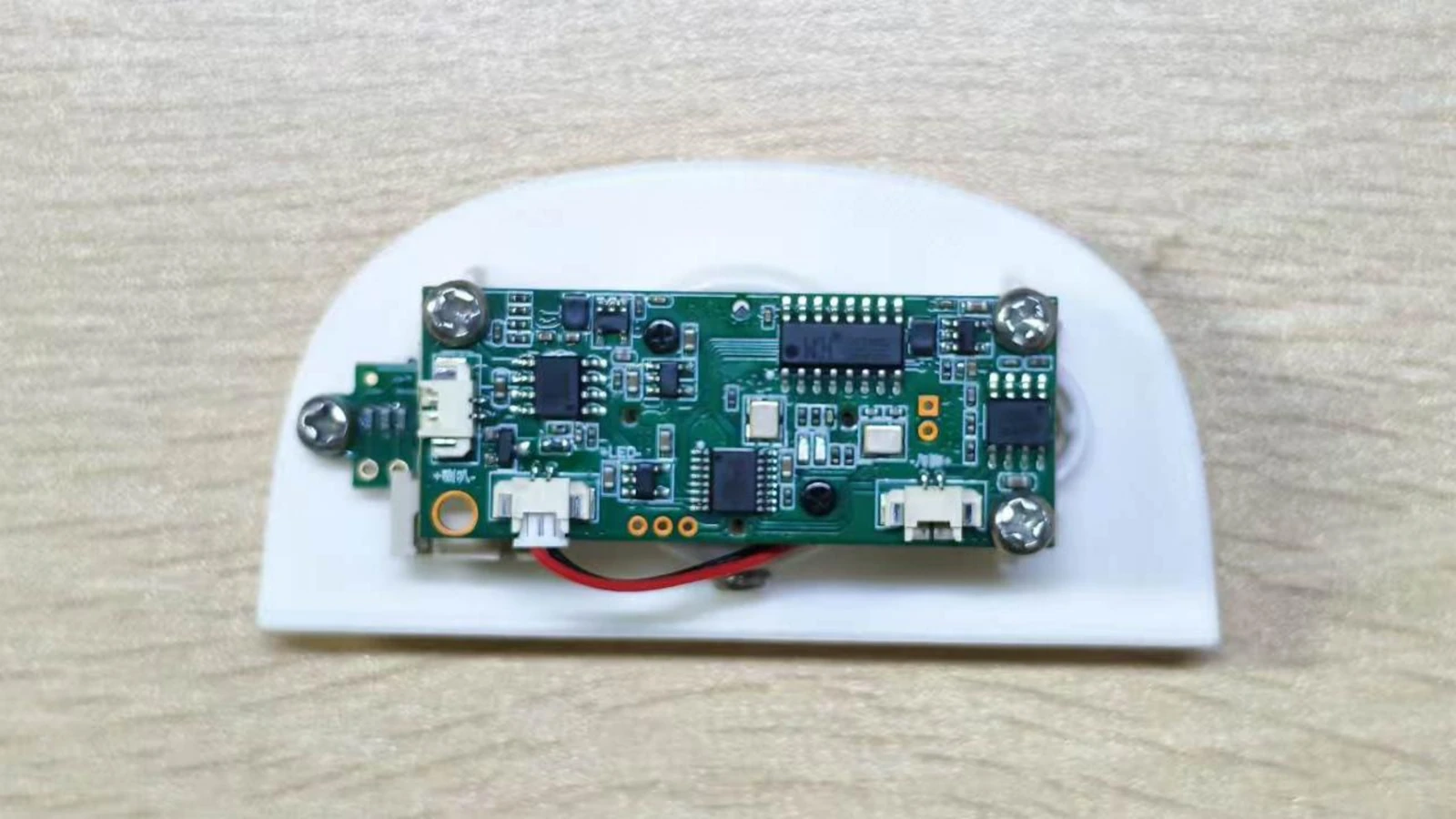
07 · Connect the light and speakers
Insert the fill-light plug into its connector on the camera/audio board.
Connect the two speakers to their corresponding connectors. Check that every plug is fully seated.
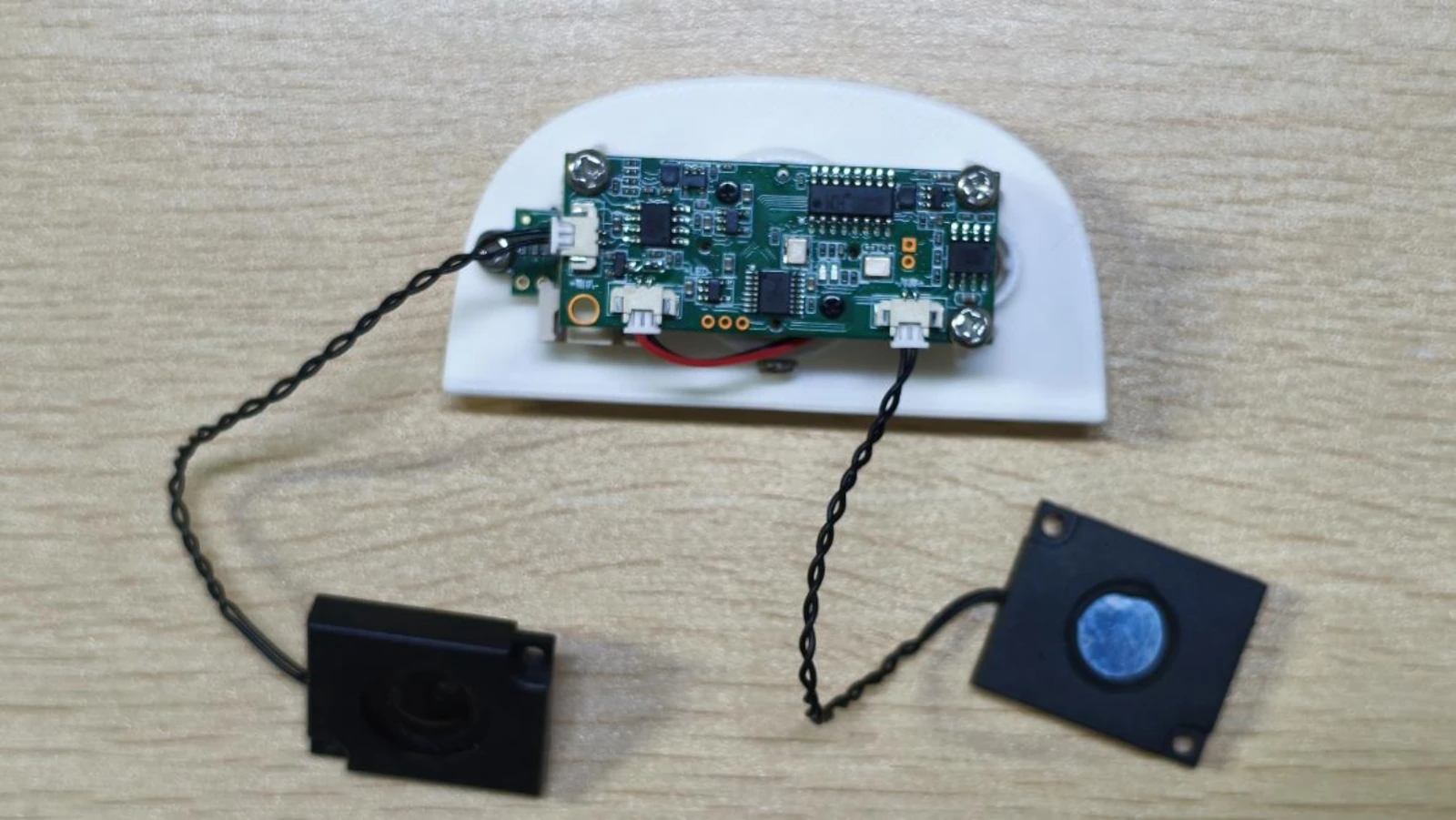
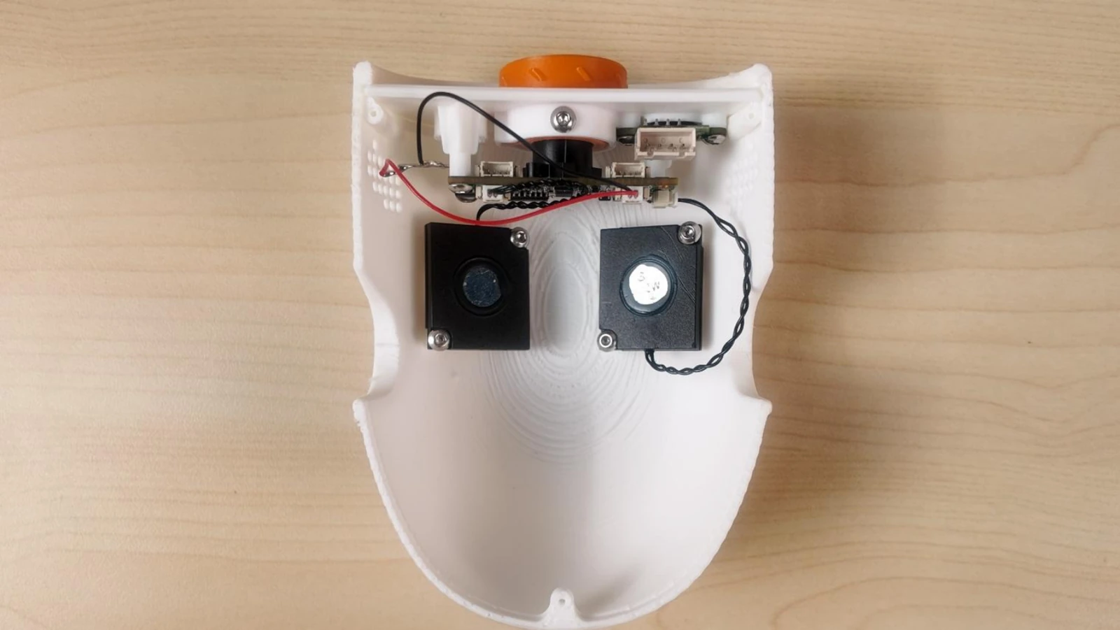
08 · Fit the head shell and harness
Place the speakers inside the head shell. Fit the camera assembly to the front panel.
Arrange the harness inside the shell, checking connector direction and leaving the wires clear of fixing holes.
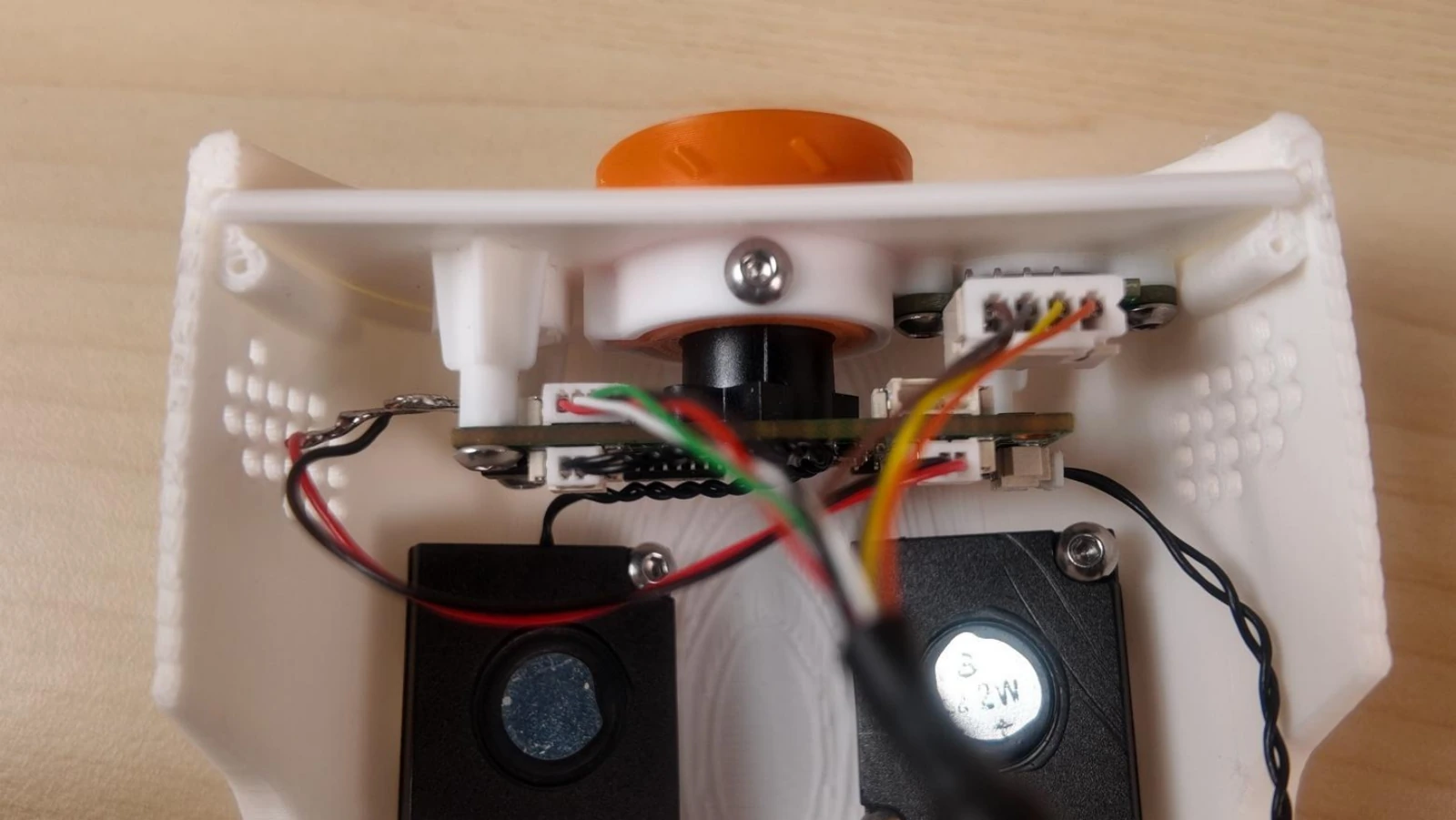
09 · Route through the bracket
Pass the main harness through the opening in the white bracket.
Leave enough slack for head movement; route the harness clear of screw holes and moving joints.
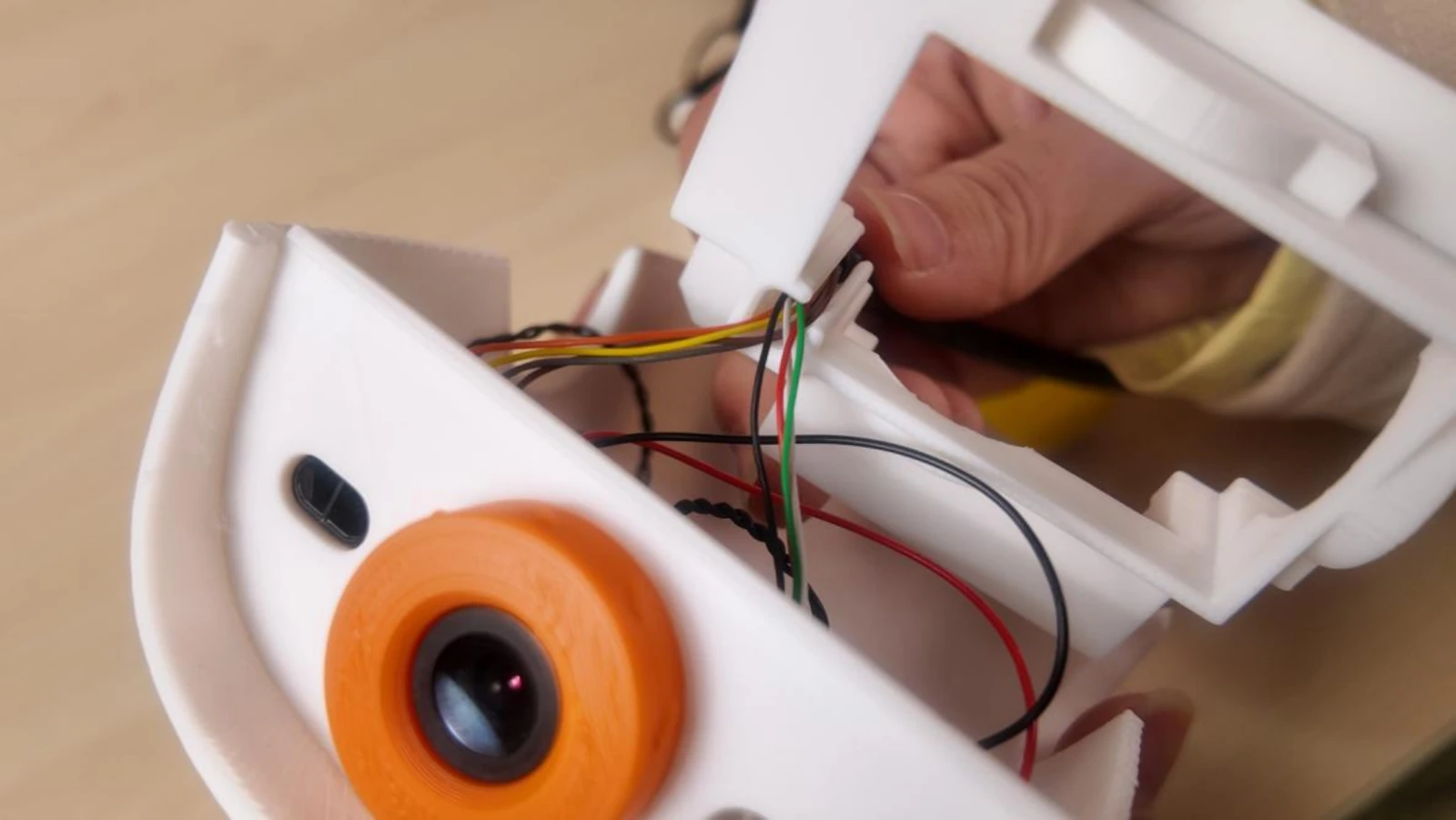
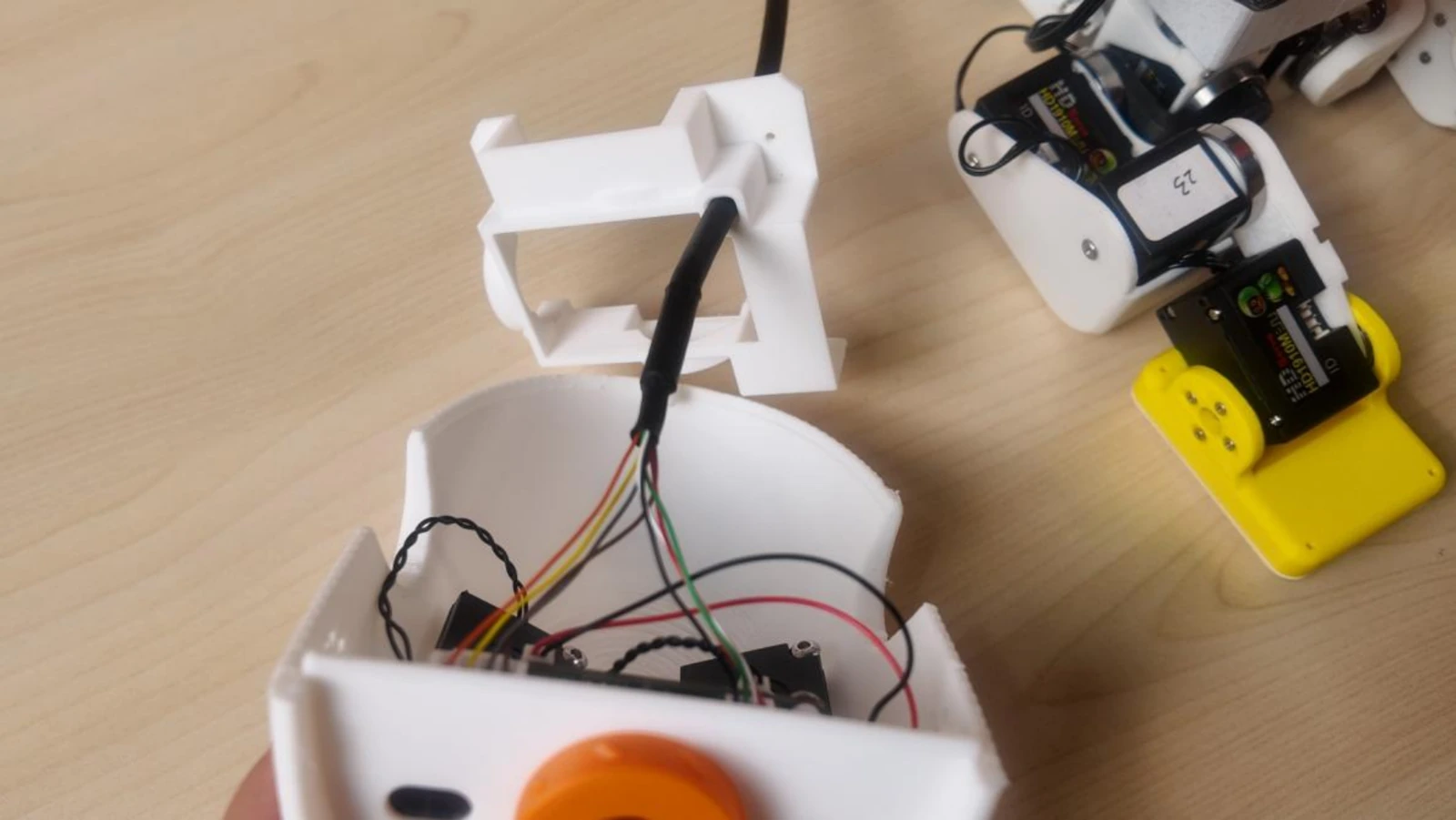
10 · Install the servo assembly and bracket
Place the servo assembly and white bracket into the orange head structure.
Secure them with M2 × 6 screws and keep the harness outside the clamping surfaces.
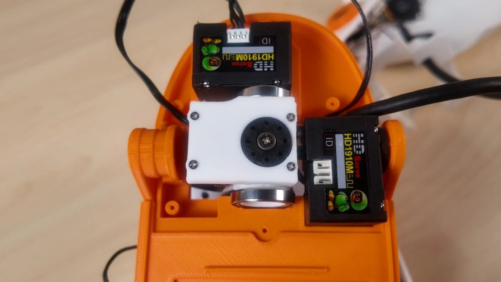
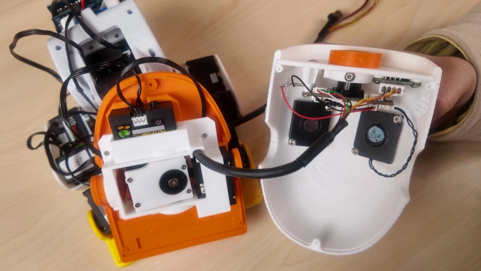
11 · Close the head shell
Align the shell and fixing holes without pinching any wires.
Install two bottom screws and one top screw, using M2 × 6 screws.
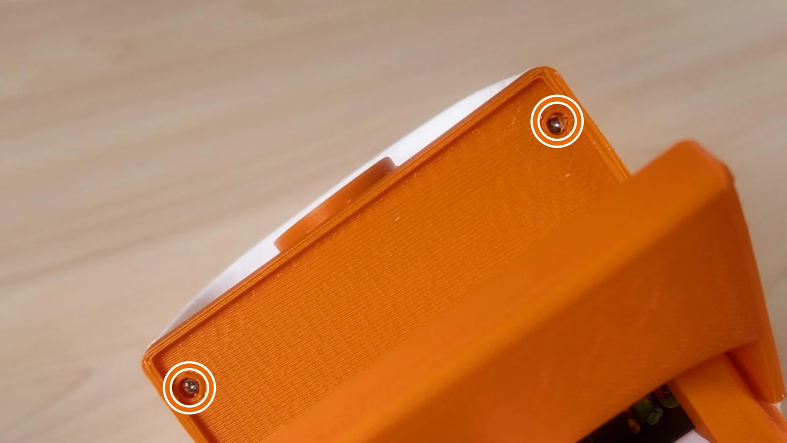
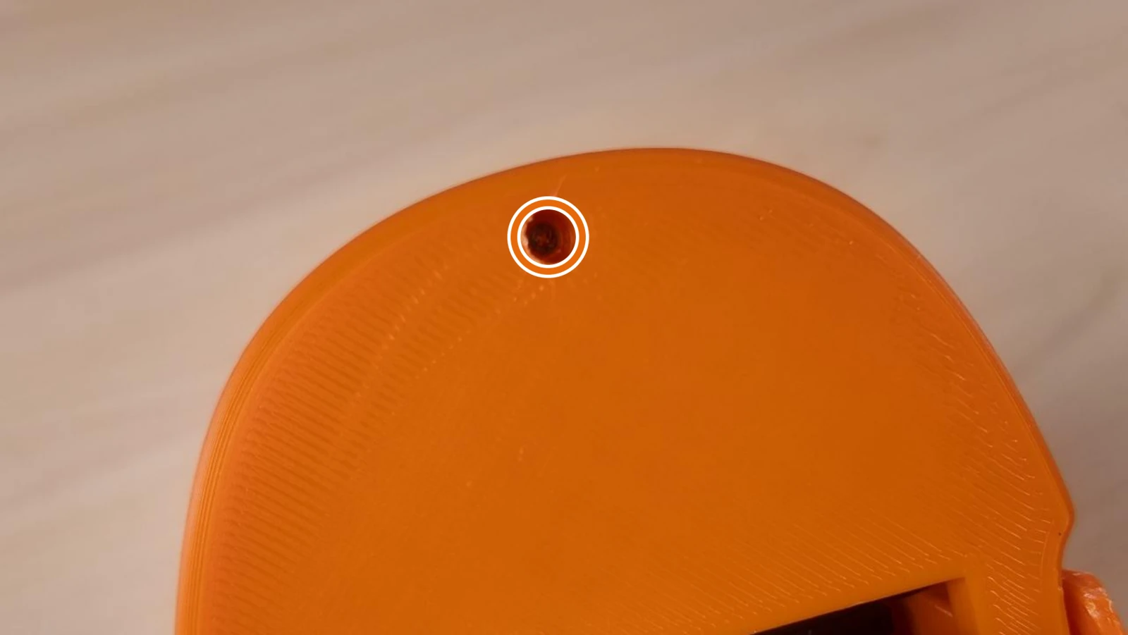
12 · Connect the USB-C cable
Connect the USB-C to USB-C cable to the controller as illustrated.
Seat both ends securely and keep the cable clear of moving joints.
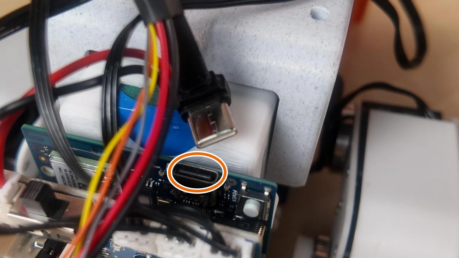
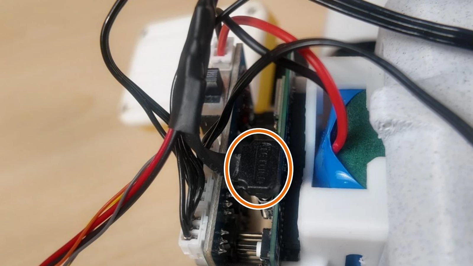
13 · Remove the connector cap
With power still disconnected, remove the white protective cap from the connector shown.
Keep the cap and expose the connector for the wiring harness.
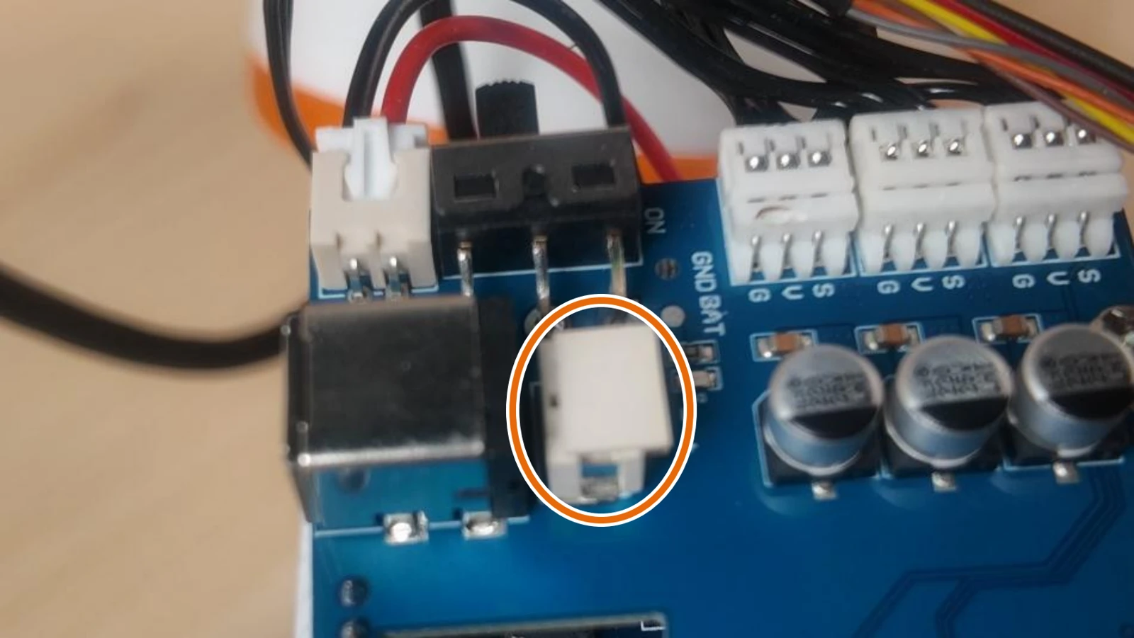
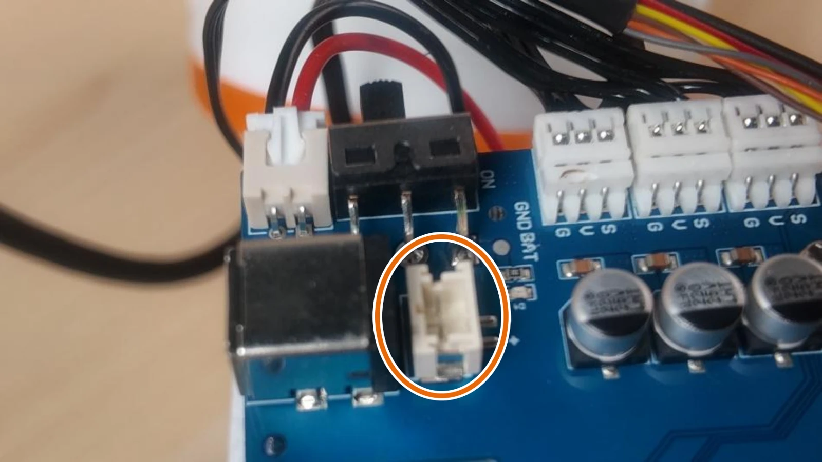
14 · Connect the main-board harness
Connect the red-and-black two-wire plug to the exposed two-pin power connector.
Connect the multi-wire harness to the connector below it; check orientation against the photos.
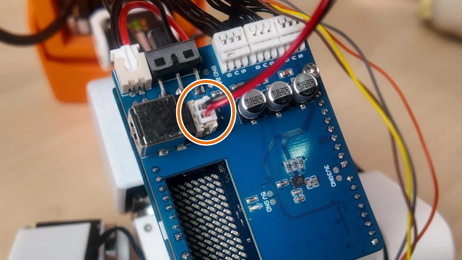
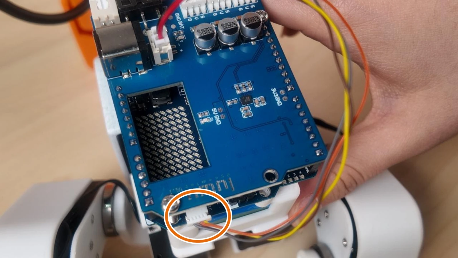
15 · Check the completed installation
Check all fasteners and confirm that every plug is secure, no bare pins touch and no wire is pinched.
Move the unpowered joints carefully to check cable slack. After calibration and binding, verify camera images, the light, speakers, microphone and live ToF ranging.
For offline use, download the English audio/video installation PDF (16 pages, about 6.8 MB). It includes all 15 steps with English instructions and captions, using the photographs updated on 13 November 2026.
Check the complete-kit wiring
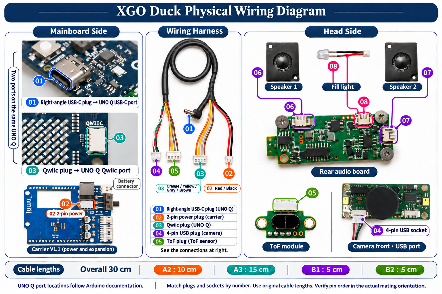
| Cable / label | Destination | Check |
|---|---|---|
| 01 · Right-angle USB-C | UNO Q USB-C port | Seat firmly; leave slack at the head |
| 02 · Red-and-black two-wire plug | Blue carrier board two-pin power connector | Check the connector key and diagram before powering on |
| 03 · Qwiic | UNO Q Qwiic connector | Sensor bus connection |
| 04 · Four-pin USB harness | Front camera-board four-pin USB connector | Check plug direction |
| 05 · ToF cable | ToF sensor | 3.3 V I²C on Wire1 |
| 06 / 07 · Speaker cables | Matching connectors on the camera module board | Connect both speakers as shown in the installation photos |
| 08 · Fill-light cable | Matching connector on the camera module board | Follow the installation photos; no exposed pins touching |
Before applying power. Do not infer polarity from wire colors alone. Match the keyed connector, pin labels and diagram. ToF uses 3.3 V; do not connect it to 5 V. Ensure no cable crosses a joint or is trapped under a screw.
Completion check
Body fasteners and the 15 servo IDs match the illustrations.
Camera, both speakers, microphone module, light and ToF are fitted and connected.
Joints have free travel and cables have slack; support the robot before powering on.