
Firmware Guide
RIG-Hover firmware is part of the RIG-Omni ESP32-S3 multi-robot firmware project.
Upstream repository: LuwuDynamics/rig_omni
User Flashing
For regular users, use the official flashing page:
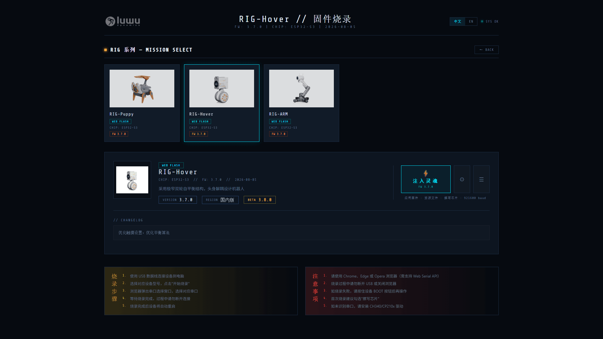
https://tools.luwudynamics.aiSteps:
- Connect the board to the PC with a USB cable; connect the battery and turn on the power switch.
- Open the page in a browser that supports the Web Serial API (Chrome / Edge / Opera).
- Select the RIG series, then pick your model (e.g. RIG-Hover) to open its flash detail page.
- Click ⚡ 注入灵魂 FW 3.7.0 to start flashing.
- Choose the matching serial port in the browser pop-up.
- Wait for the progress to finish (view the log via ☰). Do not disconnect during flashing. On first flash, tick 擦写芯片 (Erase Flash) in ⚙ 烧录参数 if you want a clean install.
- The device will restart automatically when done.
Notes:
- Connect the battery and turn on the power switch while flashing.
- If the serial port is not recognised, install the CH340/CP210x USB serial driver.
- Hold the robot after flashing because it may reboot.
Build From Source
Requirements:
- ESP-IDF v5.5.2 or newer.
- Python 3.8 or newer.
- ESP32-S3 development environment.
- Recommended module: ESP32-S3 with 16 MB Flash and PSRAM.
Clone and configure:
git clone https://github.com/LuwuDynamics/rig_omni.git

cd rig_omni

source ~/esp/esp-idf/export.sh

idf.py set-target esp32s3

idf.py menuconfig
Select:
RIG-Omni -> Board Type -> RIG-HoverThe generated configuration should contain:
CONFIG_BOARD_TYPE_HOVER=yBuild, flash, and monitor:
idf.py build

idf.py -p /dev/ttyUSB0 flash monitor
Windows example:
idf.py -p COM5 flash monitorGenerate a release firmware package:
python tools/gen_bin_package.pyFirmware Architecture
RIG-Omni uses a shared application layer and board-specific robot layers.
application.cc/.h       lifecycle, audio, display, network, OTA, MCP

mcp_server.cc/.h        remote tool framework

boards/common/          shared IMU, BLE, button, camera, battery drivers

boards/hover/           RIG-Hover board, balance control, Web tuning

display/                LCD, LVGL, EAF expression animation

audio/                  wake word, microphone, speaker, processing

tools/                  release packaging and asset tools
Hover Source Map
File | Role |
| Board startup, LCD, buttons, camera, UART, IMU, MCP tools |
| Motor protocol, servo command, wheel feedback, LQR loop, BLE/XGO command parsing |
| Shared declarations for Hover control variables and functions |
| Web UI, |
| Pin configuration |
| Board type selection |
| Build target and output naming |
Startup Chain
HoverBoardis registered through:
DECLARE_BOARD(HoverBoard);The initialization sequence is approximately:
InitializeSpi()

InitializeLcdDisplay()

InitializeButtons()

InitializeTools()

InitializeCamera()

InitializeUart()

InitializeController()

InitializeBootButton()

imu_init()

create xgo_control task

create xgo_rx task

create imu_read_once task
Normal startup logs should include:
Initialize UART

XGO control tasks created

IMU control tasks created

Initialization complete

Debug server started at http://<device-ip>
Pin References
Current Hover firmware references include:
#define XGO_UART_TX_PIN GPIO_NUM_46

#define XGO_UART_RX_PIN GPIO_NUM_38

#define TOUCH_BUTTON_GPIO GPIO_NUM_3

#define IMU_I2C_SDA GPIO_NUM_14

#define IMU_I2C_SCL GPIO_NUM_48
Verify these against the final PCB revision before publishing manufacturing files.