
Replication Guide
RIG-Arm is a 5-axis desktop arm from the RIG series, built on dual-axis dual-UART bus servos and an ESP32-S3 RIG mainboard. It ships with closed-loop inverse kinematics and an MCP tool framework for voice interaction, expression display, and precise motion control. This guide explains the maker workflow from sourcing and printing to flashing and calibration.
Skill Level
You should be comfortable with:
- 3D printing and slicer settings.
- Assembling small printed parts with self-tapping screws.
- Handling FPC cables and UART servo wiring.
- Basic lithium battery safety.
- USB serial flashing and following technical checklists.
Phase 1: Prepare Parts
Core electronics kit
For compatibility, we recommend the official integrated RIG-Arm electronics kit:
Item | Model / Spec | Qty | Notes |
Mainboard | RIG mainboard | 1 | ESP32-S3, integrated 1.09" TFT (240x240), mic, MAX98357 amp, QMI8658C IMU |
Bus servos | Dual-axis dual-UART | 5 | UART protocol, ID addressing, clutch protection |
Battery | 2S 7.4 V Li-po | 1 | With protection board |
Display | 1.09" TFT | 1 | 240x240 |
Camera | GC0308 | 1 | DVP interface, 0.3 MP |
Speaker | 8 ohm 2 W | 1 | Voice output |
Touch sensor | - | 1 | Calibration / interaction |
Power system
- Servos: 5 UART bus servos (ID addressing, 3-wire interface, dual-axis dual-output).
- Battery: 2S 7.4 V soft-pack Li-po with protection board.
- Power routing: the battery feeds two paths - one through the mainboard's 5 V buck regulator for the board, one direct to the servos (7.4 V).
Important: never power the servos from the mainboard 5 V pins. Servos need 7.4 V; on 5 V they will be weak or not move at all.
Fasteners and hardware
- Self-tapping screws M2x6 flat head x57 (with spares).
- Machine screws M2x8 round head x1 (neck pitch horn), M2x6 round head x5 (servo horns).
- Hex socket screws M3x18 x6 (base top plate / base).
- Servo extension cables: 90 mm x4, 200 mm x1 (upper arm, J2-J3).
- Flange bearings F6700zz x1 (neck pitch), F6703 x4.
- Aluminum extrusion 20x20, 50 mm x4; silicone anti-slip pads 10 mm x1 mm x4.
Phase 2: Print Mechanical Parts
Download models: MakerWorld - LuwuDynamics
Recommended settings:
Parameter | Recommendation | Notes |
Material | PLA+ or PETG | PLA+ is easiest; PETG is tougher |
Layer height | 0.2 mm (Standard) | Balance of precision and speed |
Infill | 15%-20% | Spiral/Gyroid |
Wall thickness | 1.2 mm (3 walls) | Structural strength |
Support | Required | Presets included for supported parts |
Printed parts overview - the full kit is 27 printed part types (about 34 pieces including multiples). Main groups:
- Base group: base, rotating platform, top plate (x3).
- Arm group: shoulder frame and cover, upper arm, elbow frame and base, forearm, wrist adapters and covers (x10).
- Head group: head shell, rear cover, camera ring, neck servo arm, screen base and cover (x6).
- Details: decorative antennas (x4), wrist decoration, wrist brace, 2020 extrusion caps (x4), electronics tray (x7).
After printing, deburr the holes with a file so servos install smoothly. Use the parts list in the download package from the MakerWorld page as the authoritative reference.
Phase 3: Electronics Bench Test
Before closing the shell, verify every function on the bench:
- Connect the mainboard, servos, display, camera, speaker, touch sensor, and battery.
- Flash official firmware or a known-good developer build (see Phase 5).
- Confirm the screen lights up with the boot animation.
- Confirm all five servos respond and the arm can return to center.
- Confirm the camera, microphone, and speaker are detected.
- Keep the servos unloaded during the first tests.
Phase 4: Assembly
Assembly video:
The servos are bus servos. Confirm the IDs before installation (usually pre-labeled from the factory):
ID | Joint | Function |
1 | J1 (base rotation) | Waist rotation, turns the whole arm horizontally |
2 | J2 (upper arm) | Shoulder pitch, raises / lowers the arm |
3 | J3 (forearm) | Elbow pitch, swings the forearm |
4 | J4 (wrist) | Wrist rotation, sets the end-effector heading |
5 | J5 (head/gripper) | End rotation, sets the end-effector pitch |
Important: assemble strictly by ID and direction - a wrong ID or direction can damage the servos and structure when powered on.
Phase 5: Flash Firmware
Official kits (loose parts) ship without firmware - flash it yourself after assembly; complete units ship pre-flashed. This phase is also the reference for later firmware upgrades or custom builds.
Use the official flashing page at https://tools.luwudynamics.ai (a browser with Web Serial support - Chrome / Edge / Opera - is recommended):
- Connect: attach the mainboard to your computer with a USB data cable, and connect the battery and switch it on.
- Select series: on the home page, click the RIG series card.
- Select model: pick RIG-ARM in the device list to open its flashing page.
- Start flashing: click the "Inject Soul FW 3.7.0" button.
- Pick the serial port in the browser prompt.
- Wait for completion (check the log panel as needed). Do not disconnect during flashing; to wipe old settings, enable "Erase chip" in the flashing parameters.
- Auto reboot: the device restarts automatically when done.
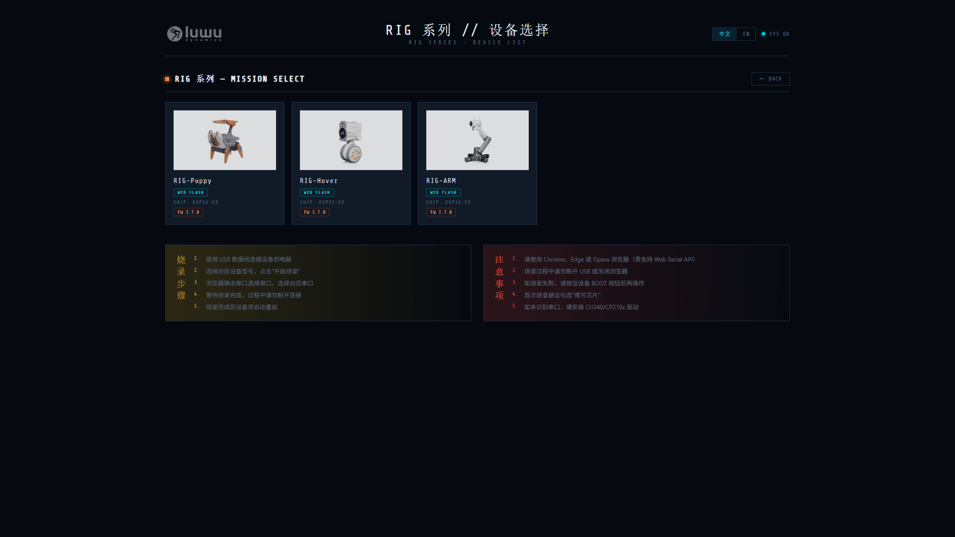
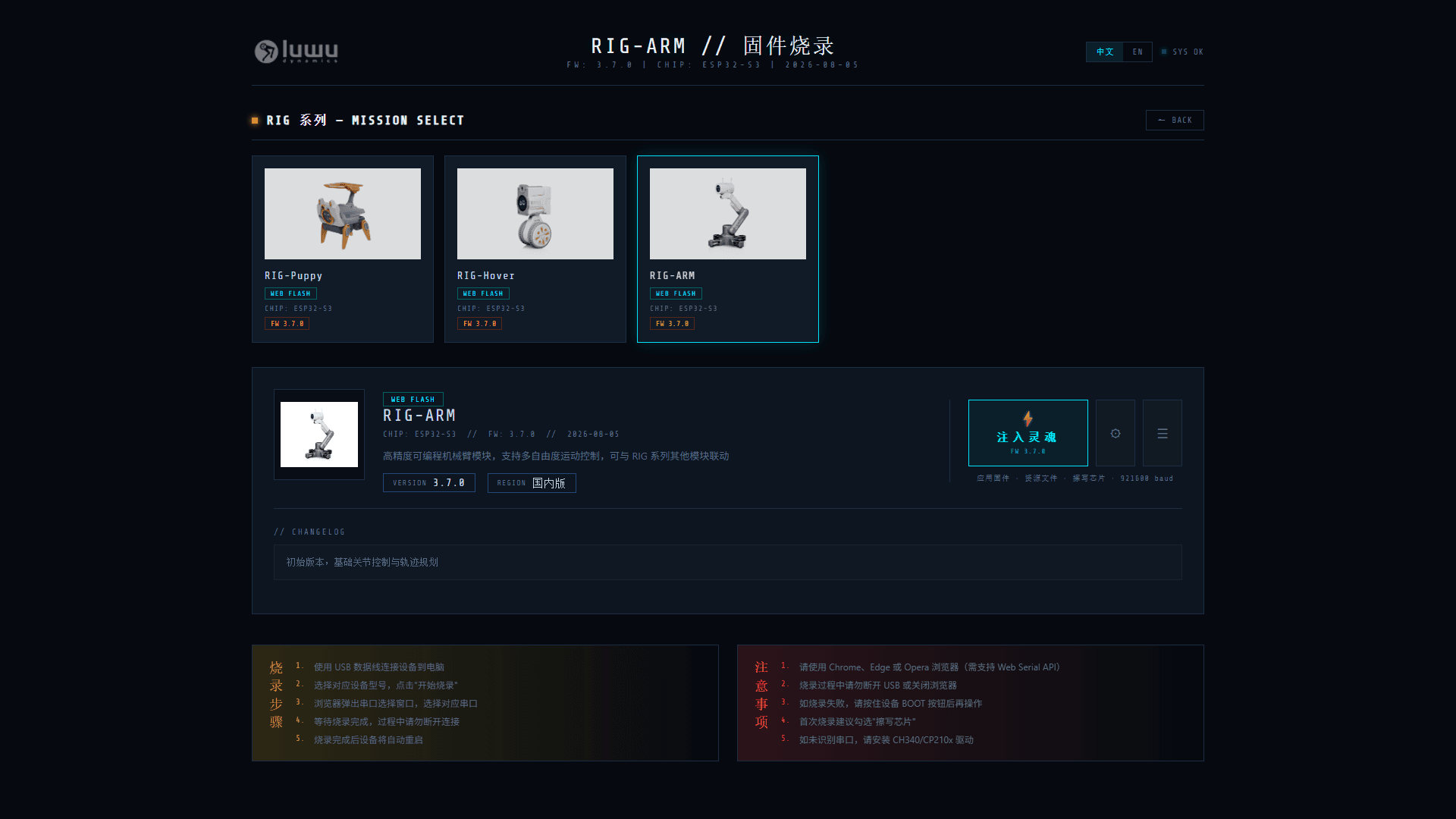
Notes:
- Use Chrome, Edge, or Opera (Web Serial API required).
- Do not disconnect USB or close the page during flashing.
- If flashing fails, hold the BOOT button while connecting.
- Enable "Erase chip" on first flash; install the CH340/CP210x driver if no serial port appears.
Phase 6: Servo Calibration
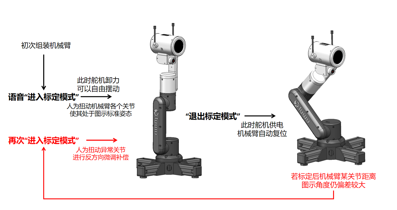
Calibration records each servo's neutral zero point with the arm in the standard upright pose. Touch the sensor once to enter calibration (servos power off so you can pose the arm by hand), set every joint to the standard upright position, then touch again to save and resume. Calibration data persists in flash and is reloaded at boot.
After calibration, continue with 02-Quick-Start to provision Wi-Fi and set up AI voice interaction.
Battery Care
For long storage, keep the charge at about 50% and avoid over-charging or deep discharge. Charge with the original or a reputable 2S balance charger. A full charge takes about 2-3 hours and powers roughly 2-3 hours of operation.