
Developer Guide
This guide is for embedded developers who want to understand, customize, and extend RIG-Arm. The project source is LuwuDynamics/rig_omni; RIG-Arm is the 5-axis desktop arm form factor in this ESP32-S3 firmware framework.
Architecture #
RIG-Arm adopts a highly integrated single-chip architecture. All sensing, control, and AI logic run on a single ESP32-S3 — no external co-processor is needed. This approach delivers high performance while reducing component count and simplifying development.
The project provides open-source resources including schematics, 3D models, firmware code and component lists, plus an assembly tutorial. It is well suited for learning motion control, large-language-model integration, multi-modal systems, and IoT communication.
Hardware Abstraction Layer
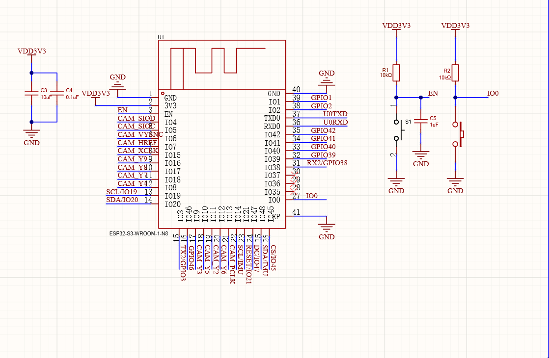
- MCU: ESP32-S3-WROOM-1-N16R8 (Dual-core 240 MHz, 2.4G Wi-Fi + BLE 5.0, 16 MB Flash, 8 MB PSRAM)
- Motion bus (UART): TX/RX serial bus driving 5 SCS009 serial servos, with ID-based addressing and status feedback. All 5 servos are daisy-chained on the same signal bus.
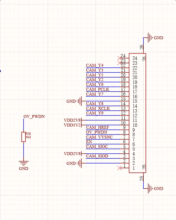
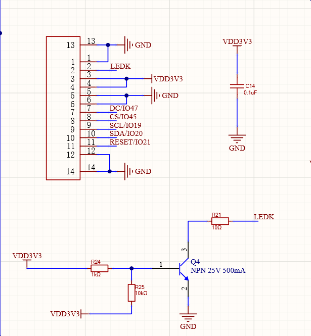
- Vision link (DVP/SPI): GC0308 camera captures images via DVP interface; GC9A01 240×240 round LCD refreshes expressions over SPI.
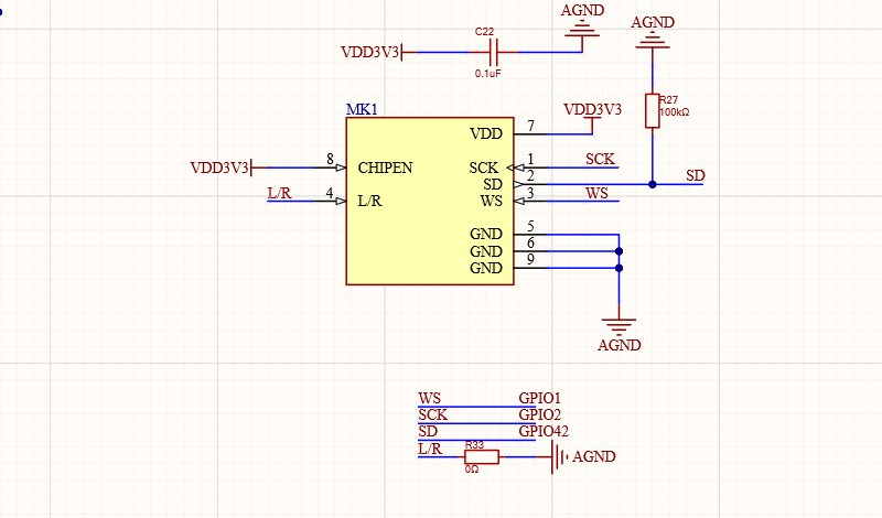
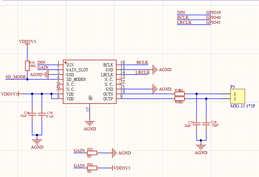
- Audio system (I²S): INMP441 MEMS digital microphone for audio input; MAX98357A amplifier drives an 8 Ω 2 W speaker.
- Attitude sensing (I²C): On-board 6-axis IMU (QMI8658C) for real-time attitude detection and motion assistance.
Main controller
Vision link — camera & display
Audio system — microphone & amplifier
Hardware Map
Module | Code entry | Notes |
Main controller | ESP32-S3 | ESP-IDF, FreeRTOS, Wi-Fi, audio, display, motion control |
Display | GC9A01 240x240 round LCD | SPI + EmoteDisplay + EAF expressions |
Servos x5 | scs009 bus servos | UART protocol, IDs 1-5, ID addressing, clutch protection |
IMU | QMI8658C | I2C roll/pitch/yaw for collision attitude detection |
Audio | I2S mic / speaker | Wake word, ASR/TTS, prompt tones |
Camera | GC0308 | DVP, 0.3 MP, optional snapshot tools |
Buttons / touch | Boot GPIO0 + Touch GPIO3 | Provisioning, chat toggle, long-press NVS reset, calibration |
Shared pins live in main/boards/common/config.h; Arm-specific pins in main/boards/arm/board_config.h:
XGO_UART_TX → GPIO 46

XGO_UART_RX → GPIO 38

LASER_GPIO   → GPIO 3

TOUCH_GPIO   → GPIO 3

IMU_I2C_SDA  → GPIO 14

IMU_I2C_SCL  → GPIO 48
Project Structure
main/boards/arm/

├── arm_board.cc          ← main logic (init, buttons, MCP tools)

├── board_config.h        ← servo / IMU / touch pins

├── ik.h / ik.cc          ← inverse kinematics solver (CLIK)

├── xgo.h / xgo.cc        ← servo protocol + control loop

├── xgo_action.h / xgo_action.cc  ← preset actions

├── ble_remote_control.h / ble_remote_control.cc  ← BLE remote control

├── arm_startup.ogg       ← startup sound

├── emoji/                ← EAF expression assets

└── wakenet/              ← wake word model
Start with these four files:
main/boards/arm/arm_board.cc- board init, button logic, MCP tool registration.main/boards/arm/xgo.cc- servo protocol, control loop, IK invocation.main/boards/arm/ik.cc- IK solver parameters and algorithm.main/Kconfig.projbuild- board selection and build options.
Build and Flash
Prerequisites: ESP-IDF v5.5.3+, Python 3.8+, an ESP32-S3 with 16 MB flash + PSRAM recommended.
git clone https://github.com/Xgorobot/RIG-Omni.git

cd RIG-Omni
Load the ESP-IDF environment:
# Windows PowerShell

. C:\Users\<user>\esp\esp-idf\Export.ps1
# macOS / Linux

source ~/esp/esp-idf/export.sh
With VS Code + the Espressif IDF extension, the environment activates automatically when you open the project.
Set the target and board:
idf.py set-target esp32s3

idf.py menuconfig

# RIG-Omni → Board Type → (X) RIG-Arm
Or set it directly in sdkconfig: CONFIG_BOARD_TYPE_ARM=y.
Build, flash, and monitor (replace the port with your actual port):
idf.py -p COM3 build flash monitor
If flashing sticks at Connecting...:
- Hold the Boot button on the back of the board.
- Tap the RST button once.
- Release RST first, then Boot - download starts immediately.
Success looks like:
Writing at 0x00010000... (100%)

Leaving...

Hard resetting via RTS pin...
The screen lights up with the boot animation. To produce a release firmware package: python tools/gen_bin_package.py (output name rig-arm, set in main/CMakeLists.txt).
Board Startup
The board class is ArmBoard in arm_board.cc, registered through DECLARE_BOARD(ArmBoard). The constructor initializes in this order:
InitializeSpi() → InitializeLcdDisplay() → InitializeButtons() → InitializeTools()

→ InitializeCamera() → InitializeUart() → InitializeLaser() → InitZeroPos()

→ ReadServoVoltage(1) → EnableStallDetection(true) → InitializeBootButton()

→ imu_init() → rig_arm_ik_init(&arm_ik, 0.05)

→ xgo_task / xgo_rx_task created
Task | Interval | Core | Purpose |
xgo_task | 2 ms | Core 0 | xgo_control(): IK solve + servo angle commands |
xgo_rx_task | 20 ms | Core 1 | xgo_rx() + imu_read_once(): servo feedback, IMU update |
Application | - | - | Voice, networking, expressions (application.cc) |
Verify these boot logs first: Initialize UART, XGO control tasks created, Initialization complete.
Motion Control
Motion control lives in xgo.cc and ik.cc. The arm uses CLIK (Closed-Loop Inverse Kinematics) to solve end-effector poses into 5 joint angles in real time on the ESP32-S3.
Key IK parameters (ik.cc)
Constant | Value | Meaning |
H0 | 0.053 m | Base height |
L1 / L2 | 0.090 m | Upper arm / forearm length |
EE_X / EE_Y / EE_Z | 0.035 / -0.01 / 0.025 m | End-effector offsets |
DEFAULT_LAM | 0.05 | DLS damping |
MAX_ITER_WARM / COLD | 40 / 60 | Max iterations (warm / cold start) |
Joint limits (radians)
Joint | Min | Max | Approx. |
J1 base rotation | -2.62 | 2.62 | ±150° |
J2 shoulder pitch | -1.57 | 1.57 | ±90° |
J3 elbow pitch | -0.50 | 2.50 | -28.6° to 143.2° |
J4 wrist rotation | -1.50 | 1.50 | ±86° |
J5 gripper/head | -1.20 | 1.30 | -68.8° to 74.5° |
Control loop (xgo_control)
- Wait for
init_flag. - If
Action_ID == 0: callarm_ik_update()to solvearm_angle[]fromarm_x/y/z/roll/pitch/yaw. - If
Action_ID != 0: play the preset action viaxgo_action(). - If not in calibration: send angles via
SetMotorAngle(arm_angle, motor_speed). - Periodically: read servo feedback, detect triple-click, read battery voltage.
MCP tool / remote → arm_x, arm_y, arm_z, arm_roll, arm_pitch, arm_yaw

  → rig_arm_ik_solve(&arm_ik, x, y, z, roll, pitch, yaw, w, q_out, ...)

    → fkChain (forward kinematics)

    → jacobian (analytic Jacobian)

    → dlsStep (damped least squares)

  → arm_angle[0..4] = q_out (degrees)
Servo protocol
scs009 servos use the XGO serial protocol on UART2 at 500 kbps; all 5 servos share one bus and are addressed by ID. Key functions: SetMotorAngle(angle[], vel), ReadMotorState(ID), InitZeroPos() / WriteZeroPos(), EnableAllMotor(mode), EnableStallDetection(bool).
Calibration flow
Calibration records each servo's neutral zero point:
- Single-click the touch sensor to enter calibration (servos power off; pose the arm by hand).
- The screen shows the calibration expression.
- Move every joint to the standard upright position.
- Touch the sensor again to exit - zero points are written to flash (0xFFF000) and restored by
InitZeroPos()at boot.
MCP Tools
RIG-Arm registers these tools in InitializeTools():
MCP tool | Parameters | Action |
self.arm.node | - | Nod up and down |
self.arm.shake | - | Shake left and right |
self.arm.x | x: -3 to 3 | Move end forward/backward (cm) |
self.arm.y | y: -2 to 2 | Move end left/right (cm) |
self.arm.z | z: -5 to 5 | Move end up/down (cm) |
self.arm.yaw | yaw: -60 to 60 | Rotate end left/right (deg) |
self.arm.pitch | pitch: -30 to 30 | Pitch end (deg) |
self.arm.roll | roll: -30 to 30 | Tilt end (deg) |
self.dog.calibrate | mode: 0/1 | Enter/exit calibration |
Tuning
Verify servo directions without load first, then tune motion parameters.
- Before tuning: calibration done (screen shows neutral), IDs 1-5 map to J1-J5, IMU readable via
GetDeviceStatusJson, all joints move freely by hand. - Joint limits: edit the
LIMarray inik.cc(radians; degrees x pi / 180). Confirm mechanical limits by hand first. - If IK does not converge (
Not convergedin logs): raiseDEFAULT_LAM(0.05 → 0.1), check the target is inside the workspace, and verify H0/L1/L2/EE_* match your build. - Safe ranges: end position about x -8 to +8 cm, y -5 to +5 cm, z 5 to 23 cm; end rotation yaw ±90°, pitch ±60°, roll ±60°. MCP tools already clamp increments; test small before changing constants.
Extension Patterns
Register a new MCP action
Implement the motion in xgo_action.cc, then register it in arm_board.cc:
mcp_server.AddTool("self.arm.look_around",

    "When the user asks what is around, slowly turn to observe",

    PropertyList({}),

    [this](const PropertyList& properties) -> ReturnValue {

        look_around();

        return true;

    });
Prefer parameterized tools so the AI can set amplitude and speed. Never block or vTaskDelay() for long inside MCP callbacks.
Keyframe-based preset action
void draw_circle() {

    const int time = 3000;

    const float radius = 0.03f;

    for (int t = 0; t <= time; t += 10) {

        float phase = 2.0f * M_PI * t / 3000.0f;

        float x = 0.10f + radius * cos(phase);

        float y = radius * sin(phase);

        float q_out[5];

        rig_arm_ik_solve(&arm_ik, x, y, 0.15f, 0, -0.3f, 0, 0.65f, q_out, NULL, NULL);

        SetMotorAngle(q_out, 10);

        vTaskDelay(pdMS_TO_TICKS(10));

    }

}
Adapt to modified mechanics
After changing shell or link lengths, edit the constants in ik.cc (H0/L1/L2/EE_X/EE_Y/EE_Z, meters) - the IK solver adapts automatically - and review the LIM array.
Expressions and boot behavior
- Add EAF files to
main/boards/arm/emoji/; the file name (without extension) is the expression name. Calldisplay_->SetEmotion("name"). - Startup expression and sound:
OnStartup()inarm_board.cc(SetEmotion("launch"),PlaySound(ARM_STARTUP_SOUND)). - Button behavior:
InitializeButtons()- single click toggles chat/provisioning, long-press 1 s shows nvs_reset, 3 s clears NVS; touch sensor toggles calibration.
Development Safety
- Wrong servo IDs, wrong zero points, or reversed directions cause abnormal motion or collisions - a 5-axis serial arm has no tolerance for it.
- Drive motion through
arm_x/y/z/roll/pitch/yaw(IK), not by writing servo angles directly. - Do not add logging floods, dynamic allocation, or slow network calls inside
xgo_control()- it runs every 2 ms. - Verify servo directions without load before tuning motion parameters.
- After menuconfig changes, run
idf.py fullcleanif the build misbehaves.
Reference
- Repository: LuwuDynamics/RIG-Omni
- Arm board entry: main/boards/arm/arm_board.cc
- Arm control: main/boards/arm/xgo.cc
- Arm IK solver: main/boards/arm/ik.cc
- Pin config: main/boards/arm/board_config.h
- Build options: main/Kconfig.projbuild
- ESP-IDF docs: Espressif ESP-IDF Programming Guide
- 3D models: MakerWorld - LuwuDynamics